ford Workshop Repair Guides

Ford Workshop Service and Repair Manuals

Parking, Rear and License Plate Lamps > < Stoplamps
Exterior Lighting - Turn Signal and Hazard Lamps Fiesta 1996 (08/1995-02/2002)
Diagnosis and Testing

Refer to Wiring Diagrams Section 417-01, for schematic and connector information.

Special Tool(s)

Terminal Probe Kit

29-011A

Inspection and Checking

  1. Verify the customer concern.
  1. Visually check the following electrical causes for the concern:

Visual Inspection Chart

Electrical
  • Fuse(s)
  • Lamp(s)
  • Connector(s)
  • Switches
  • Wiring harness
  1. Resolve any obvious causes or concerns found during the visual inspection before carrying out any further tests.
  1. If the concern persists, check the symptoms and continue with the symptom chart.

Symptom Chart

Symptom Chart

Symptom Possible Sources Action
Turn signal lamps inoperative/illuminate continuously
*
Fuse(s)
*
Circuit(s)
*
Turn signal relay
*
Multifunction switch
*
Central junction box (CJB)
*
Generic electronic module (GEM)
*
Instrument cluster
*
GO to Pinpoint Test A.
Turn signal lamps flash continuously
*
Multifunction switch
*
Generic electronic module (GEM)
*
GO to Pinpoint Test A.
One turn signal lamp inoperative / illuminate continuously
*
Circuit(s)
*
Headlamp
*
Turn signal side lamp
*
Rear lamp assembly
*
Instrument cluster
*
GO to Pinpoint Test B.
Hazard warning lights inoperative / illuminate continuously
*
Fuse(s)
*
Circuit(s)
*
Turn signal relay
*
Multifunction switch
*
Central junction box (CJB)
*
GO to Pinpoint Test C.

System Check

NOTE:
NOTE:Use a digital multimeter for all electrical measurements.

PINPOINT TEST A : TURN SIGNAL LAMPS INOPERATIVE/ILLUMINATE CONTINUOUSLY

TEST CONDITIONS DETAILS/RESULTS/ACTIONS
A1: DETERMINE THE FAULT CONDITION
1
Ignition switch in position II.
2
SWITCH OFF the turn signals and hazard warning lights
3
Check the turn signal lamps.

Do the left/right-hand turn signal lamps illuminate continuously?
Yes
No
- No turn signal lamps illuminate:GO to A2.
- All turn signal lamps flash continuously:GO to A16.
A2: DETERMINE THE FAULT CONDITION
1
SWITCH ON left-hand turn signal.
2
SWITCH ON right-hand turn signal.
3
Check the left/right-hand turn signal lamps.

Are all of the turn signal lamps inoperative?
Yes
No
- Left-hand turn signal lamps inoperative: GO to A10.
- Right-hand turn signal lamps inoperative: GO to A11.
A3: CHECK FUSE F17 (CJB)
1
Ignition switch in position 0.
2
CHECK fuse F17 (CJB) (15 A).

Is the fuse OK?
Yes
No
RENEW fuse F17 (15 A). If the fuse fails again, LOCATE and RECTIFY the short-circuit using Wiring Diagrams. CHECK the operation of the system.
A4: CHECK THE VOLTAGE AT FUSE F17 (CJB)
1
Connect fuse F17 (CJB).
2
Ignition switch in position II.
3
Measure the voltage between fuse F17 (CJB) and ground.

Does the meter display battery voltage?
Yes
No
LOCATE and RECTIFY the break in the voltage supply of fuse F17 (CJB) using the Wiring Diagrams, if necessary RENEW the CJB. CHECK the operation of the system.
A5: CHECK VOLTAGE AT THE MULTIFUNCTION SWITCH (TURN SIGNAL RELAY INPUT)
1
Ignition switch in position 0.
2
Disconnect turn signal relay.
3
Ignition switch in position II.

4
Measure the voltage between the multifunction switch, the turn signal relay socket (49), component side and ground.

Does the meter display battery voltage?
Yes
No
A6: CHECK THE VOLTAGE AT THE MULTIFUNCTION SWITCH
1
Ignition switch in position 0.
2
Disconnect multifunction switch from connector C65a.
3
Ignition switch in position II.

4
Measure the voltage between the multifunction switch, connector C65a, pin 9, circuit 14-LG5 (VT), wiring harness side and ground.

Does the meter display battery voltage?
Yes
RENEW the multifunction switch. CHECK the operation of the system.
No
LOCATE and RECTIFY the break in the circuit between fuse F17 (CJB) and the multifunction switch using the Wiring Diagrams. CHECK the operation of the system.
A7: CHECK THE MULTIFUNCTION SWITCH (TURN SIGNAL RELAY GROUND)
1
Ignition switch in position 0.

2
Measure the resistance between the multifunction switch, the turn signal relay socket (31), component side and ground.

Is less than 2 Ohm measured?
Yes
No
A8: CHECK GROUND CONNECTION OF THE MULTIFUNCTION SWITCH
1
Ignition switch in position II.
2
SWITCH ON the front wash/wipe function.
3
Check the front wash/wipe function

Is the wash/wipe function OK?
Yes
RENEW the multifunction switch. CHECK the operation of the system.
No
LOCATE and RECTIFY the break in circuit 31-LE29 (BK), between the multifunction switch and soldered connection S65, using the Wiring Diagrams. CHECK the operation of the system.
A9: CHECK THE MULTIFUNCTION SWITCH (TURN SIGNAL RELAY OUTPUT)
1
Ignition switch in position 0.
2
Disconnect multifunction switch from connector C65a.
3
SWITCH ON the left-hand turn signal.

4
Measure the resistance at the multifunction switch between the turn signal relay socket (49A), component side and connector C65a, pin 5, component side.

Is less than 2 Ohm measured?
Yes
RENEW the turn signal relay. CHECK the operation of the system.
No
RENEW the multifunction switch. CHECK the operation of the system.
A10: CHECK THE MULTIFUNCTION SWITCH
1
Ignition switch in position 0.
2
Disconnect multifunction switch from connector C65a.

3
Measure the resistance between the multifunction switch, connector C65a, pin 5, circuit 49-LG1 (BU), wiring harness side and ground.

Is more than 10,000 Ohm measured?
Yes
LOCATE and RECTIFY the break in the circuit between the multifunction switch and soldered connection S913 using the Wiring Diagrams. CHECK the operation of the system.
No
RENEW the multifunction switch. CHECK the operation of the system.
A11: CHECK THE MULTIFUNCTION SWITCH
1
Ignition switch in position 0.
2
Disconnect multifunction switch from connector C65a.

3
Measure the resistance between multifunction switch, connector C65a, pin 11, circuit 49-LG2 (BU/RD), wiring harness side and ground.

Is more than 10,000 Ohm measured?
Yes
LOCATE and RECTIFY the break in the circuit between the multifunction switch and soldered connection S914 using the Wiring Diagrams. CHECK the operation of the system.
No
RENEW the multifunction switch. CHECK the operation of the system.
A12: CHECK THE MULTIFUNCTION SWITCH
1
Ignition switch in position 0.
2
Disconnect multifunction switch from connector C65a.
3
Ignition switch in position II.
4
Check the left/right-hand turn signal lamps.

Do the turn signal lamps on one side illuminate continuously?
Yes
No
- No turn signal lamp illuminates continuously: RENEW the multifunction switch. CHECK the operation of the system.
- All turn signal lamps illuminate continuously, vehicles with anti-theft warning system only: CHECK the generic electronic module (GEM) using WDS and RENEW if necessary. CHECK the operation of the system.
A13: CHECK THE INSTRUMENT CLUSTER
1
Ignition switch in position 0.
2
Disconnect fuse F2 (CJB) (7.5 A).
3
Disconnect fuse F6 (CJB) (7.5 A).
4
Disconnect fuse F13 (CJB) (15 A).
5
Disconnect fuse F19 (CJB) (7.5 A).
6
Ignition switch in position II.
7
Check the left/right-hand turn signal lamps.

Do the turn signal lamps on one side illuminate continuously?
Yes
No
RENEW the instrument cluster. CHECK the operation of the system.
A14: DETERMINE THE EQUIPMENT LEVEL
1
Determine the equipment level.

Is the vehicle equipped with an anti-theft warning system?
Yes
No
- Left-hand turn signal lamps illuminate continuously: LOCATE and RECTIFY the short to battery voltage in the circuits connected to soldered connection S913 using the Wiring Diagrams. CHECK the operation of the system.
- Right-hand turn signal lamps illuminate continuously: LOCATE and RECTIFY the short to battery voltage in the circuits connected to soldered connection S914 using the Wiring Diagrams. CHECK the operation of the system.
A15: CHECK THE GENERIC ELECTRONIC MODULE (GEM)
1
Ignition switch in position 0.
2
Connect fuse F2 (CJB) (7.5 A).
3
Connect fuse F6 (CJB) (7.5 A).
4
Connect fuse F13 (CJB) (15 A).
5
Connect fuse F19 (CJB) (7.5 A).
6
Disconnect fuse F3 (CJB) (10 A).
7
Disconnect fuse F8 (CJB) (15 A).
8
Disconnect fuse F12 (CJB) (20 A).
9
Disconnect fuse F18 (CJB) (15 A).
10
Ignition switch in position II.
11
Check the left and right-hand turn signal lamps.

Do the left/right-hand turn signal lamps illuminate continuously?
Yes
- Left-hand turn signal lamps illuminate continuously: LOCATE and RECTIFY the short to battery voltage in the circuits connected to soldered connection S913 using the Wiring Diagrams. CHECK the operation of the system.
- Right-hand turn signal lamps illuminate continuously: LOCATE and RECTIFY the short to battery voltage in the circuits connected to soldered connection S914 using the Wiring Diagrams. CHECK the operation of the system.
No
RENEW the generic electronic module (GEM). CHECK the operation of the system.
A16: CHECK THE MULTIFUNCTION SWITCH
1
Ignition switch in position 0.
2
Disconnect multifunction switch from connector C65a.
3
Ignition switch in position II.
4
Check the left/right-hand turn signal lamps.

Do all turn signal lamps flash continuously?
Yes
RENEW the multifunction switch. CHECK the operation of the system.
No
CHECK the generic electronic module (GEM) using WDS and RENEW if necessary. CHECK the operation of the system.

PINPOINT TEST B : ONE TURN SIGNAL LAMP IS INOPERATIVE

TEST CONDITIONS DETAILS/RESULTS/ACTIONS
B1: DETERMINE THE FAULT CONDITION
1
Ignition switch in position 0.
2
SWITCH ON the hazard warning lights.
3
Determine which turn signal lamp/warning lamp is inoperative.

Is one left-hand turn signal lamp/warning lamp inoperative?
Yes
- Left-hand front turn signal lamp: GO to B2.
- Left-hand turn signal side lamp: GO to B14.
- Left-hand rear turn signal lamp: GO to B8.
- Instrument cluster warning lamp for left-hand turn signal: GO to B18.
No
- Right-hand front turn signal lamp: GO to B5.
- Right-hand turn signal side lamp: GO to B16.
- Right-hand rear turn signal lamp: GO to B11.
- Instrument cluster warning lamp for right-hand turn signal:GO to B19.
B2: CHECK THE LEFT-HAND HEADLAMP
1
SWITCH ON the parking lights
2
Check the left-hand front parking lamp.

Does the left-hand front parking lamp illuminate?
Yes
No
B3: CHECK VOLTAGE AT THE LEFT-HAND FRONT TURN SIGNAL LAMP
1
Disconnect left-hand headlamp from connector C157.
2
Ignition switch in position II.
3
SWITCH ON the left-hand turn signal.

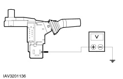
4
Measure the voltage between the left-hand headlamp, connector C157, pin 3, circuit 49-LG11 (BU/OG), wiring harness side and pin 6, circuit LE31 (BK), wiring harness side.

Does the meter display fluctuating battery voltage?
Yes
CHECK and if necessary RENEW the headlamp. CHECK the operation of the system.
No
LOCATE and RECTIFY the break in the circuit between soldered connection S913 and the left-hand headlamp using the Wiring Diagrams. CHECK the operation of the system.
B4: CHECK GROUND CONNECTION AT THE LEFT-HAND HEADLAMP
1
Disconnect left-hand headlamp from connector C157.

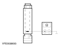
2
Measure the resistance between left-hand headlamp, connector C157, pin 6, circuit 31-LE31 (BK), wiring harness side and ground.

Is less than 2 Ohm measured?
Yes
CHECK and if necessary RENEW the headlamp. CHECK the operation of the system.
No
LOCATE and RECTIFY the break in the circuit between the headlamp and soldered connection S110 using the Wiring Diagrams. CHECK the operation of the system.
B5: CHECK THE RIGHT-HAND HEADLAMP
1
SWITCH ON the parking lights
2
Check the front right parking lamp.

Does the right-hand parking lamp illuminate?
Yes
No
B6: CHECK THE VOLTAGE AT THE FRONT RIGHT-HAND TURN SIGNAL LAMP
1
Disconnect right-hand headlamp from connector C174.
2
Ignition switch in position II.
3
SWITCH ON right-hand turn signal.

4
Measure the voltage between the right-hand headlamp, connector C174, pin 3, circuit 49-LG18 (BU), wiring harness side and pin 6, circuit 31-LE30 (BK), wiring harness side.

Does the meter display fluctuating battery voltage?
Yes
CHECK and if necessary RENEW the headlamp. CHECK the operation of the system.
No
CHECK the operation of the system. LOCATE and RECTIFY the break in the circuit between soldered connection S914 and the right-hand headlamp using the Wiring Diagrams. CHECK the operation of the system.
B7: CHECK GROUND CONNECTION AT RIGHT-HAND HEADLAMP
1
Ignition switch in position 0.
2
Disconnect right-hand headlamp from connector C174.

3
Measure the resistance between right-hand headlamp, connector C174, pin 6, circuit 31-LE30 (BK), wiring harness side and ground.

Is less than 2 Ohm measured?
Yes
CHECK and if necessary RENEW the headlamp. CHECK the operation of the system.
No
LOCATE and RECTIFY the break in the circuit between the headlamp and soldered connection S110 using the Wiring Diagrams. CHECK the operation of the system.
B8: CHECK THE LEFT-HAND REAR LAMP ASSEMBLY
1
SWITCH ON the parking lights
2
Check the left-hand rear parking lamp.

Does the left-hand rear lamp illuminate?
Yes
No
B9: CHECK THE VOLTAGE AT THE LEFT-HAND REAR TURN SIGNAL LAMP
1
Disconnect left-hand rear lamp assembly from connector:.
  • Courier: C1050(a)
  • All others: C50(a)
2
Ignition switch in position II.
3
SWITCH ON the left-hand turn signal.

4
Measure the voltage between the left-hand rear lamp assembly:
  • Courier without trailer socket: Connector C1050, pin 5, circuit 49-LG12 (BU), wiring harness side and pin 2, circuit 31-LF23 (BK), wiring harness side.
  • Courier with trailer socket: connector C1050a, pin 5, circuit (BK/WH), wiring harness side and pin 2, circuit (GN), wiring harness side.
  • All others without trailer socket: Connector C50, pin 1, circuit 49-LG12 (BU) and pin 4, circuit 31-LF23 (BK), wiring harness side.
  • All others with trailer socket: connector C50a, pin 1, circuit (BK/WH) and pin 4, circuit (GN), wiring harness side.

Does the meter display fluctuating battery voltage?
Yes
CHECK and if necessary RENEW the rear lamp assembly. CHECK the operation of the system.
No
LOCATE and RECTIFY the break in the circuit between soldered connection S913 and the rear lamp assembly using the Wiring Diagrams. CHECK the operation of the system.
B10: CHECK GROUND CONNECTION OF LEFT-HAND REAR LAMP ASSEMBLY
1
Disconnect left-hand rear lamp assembly from connector:.
  • Courier: C1050(a)
  • All others: C50(a)

2
Measure the resistance between the left-hand rear lamp assembly:
  • Courier without trailer socket: connector C1050, pin 2, circuit 31-LF23 (BK), wiring harness side and ground.
  • Courier with trailer socket: connector C1050a, pin 2, circuit (GN), wiring harness side and ground.
  • All others without trailer socket: connector C50, pin 4, circuit 31-LF23 (BK), wiring harness side and ground.
  • All others with trailer socket: connector C50a, pin 4, circuit (GN), wiring harness side and ground.

Is less than 2 Ohm measured?
Yes
CHECK and if necessary RENEW the rear lamp assembly. CHECK the operation of the system.
No
LOCATE and RECTIFY the break in circuit 31-LF23 (BK) or (GN) between the rear lamp assembly and ground G5 using the Wiring Diagrams. CHECK the operation of the system.
B11: CHECK THE RIGHT-HAND REAR LAMP ASSEMBLY
1
SWITCH ON the parking lights

Does the right-hand rear lamp illuminate?
Yes
No
B12: CHECK THE VOLTAGE AT THE RIGHT-HAND REAR TURN SIGNAL LAMP
1
Disconnect right-hand rear lamp assembly from connector:.
  • Courier: C1049(a)
  • All others: C49(a)
2
Ignition switch in position II.
3
SWITCH ON the right-hand turn signal.

4
Measure the voltage at the right-hand rear lamp assembly:
  • Courier without trailer socket: Connector C1049, pin 5, circuit 49-LG19 (BU/RD), wiring harness side and pin 2, circuit 31-LF24 (BK), wiring harness side.
  • Courier with trailer socket: connector C1049a, pin 5, circuit (BK/GN), wiring harness side and pin 2, circuit (GN), wiring harness side.
  • All others without trailer socket: Connector C49, pin 5, circuit 49-LG19 (BU/RD), wiring harness side and pin 2, circuit 31-LF24 (BK), wiring harness side.
  • All others with trailer socket: connector C49a, pin 5, circuit (BK/GN), wiring harness side and pin 2, circuit (GN), wiring harness side.

Does the meter display fluctuating battery voltage?
Yes
CHECK and if necessary RENEW the rear lamp assembly. CHECK the operation of the system.
No
LOCATE and RECTIFY the break in circuit 49-LG19 (BU/RD) or (BK/GN) , between soldered connection S914 and the rear lamp assembly using the Wiring Diagrams. CHECK the operation of the system.
B13: CHECK GROUND CONNECTION OF THE RIGHT-HAND REAR LAMP ASSEMBLY
1
Disconnect right-hand rear lamp assembly from connector:.
  • Courier: C1049(a)
  • All others: C49(a)

2
Measure the resistance between the right-hand rear lamp assembly:
  • Courier without trailer socket: connector C1049, pin 2, circuit 31-LF24 (BK), wiring harness side and ground.
  • Courier with trailer socket: connector C1049a, pin 2, circuit (GN), wiring harness side and ground.
  • All others without trailer socket: connector C49, pin 2, circuit 31-LF24 (BK), wiring harness side and ground.
  • All others with trailer socket: connector C49a, pin 2, circuit (GN), wiring harness side and ground.

Is less than 2 Ohm measured?
Yes
CHECK and if necessary RENEW the rear lamp assembly. CHECK the operation of the system.
No
LOCATE and RECTIFY the break in circuit 31-LF24 (BK) or (GN) between the rear lamp assembly and ground G3 using the Wiring Diagrams. CHECK the operation of the system.
B14: CHECK THE VOLTAGE AT THE LEFT-HAND TURN SIGNAL SIDE LAMP
1
Disconnect left-hand turn signal side lamp from connector C40.
2
Ignition switch in position II.
3
SWITCH ON the left-hand turn signal.

4
Measure the voltage between the left-hand turn signal side lamp, connector C40, pin 2, circuit 49-LG13 (BU/RD), wiring harness side and ground.

Does the meter display fluctuating battery voltage?
Yes
No
LOCATE and RECTIFY the break in the circuit between soldered connection S913 and the turn signal side lamp using the Wiring Diagrams. CHECK the operation of the system.
B15: CHECK GROUND CONNECTION OF THE LEFT-HAND TURN SIGNAL SIDE LAMP
1
Ignition switch in position 0.

2
Measure the resistance between the left-hand turn signal side lamp, connector C40, pin 1, circuit 31-LG13 (BK), wiring harness side and ground.

Is less than 2 Ohm measured?
Yes
CHECK and if necessary RENEW the turn signal side lamp. CHECK the operation of the system.
No
LOCATE and RECTIFY the break in the circuit between the turn signal side lamp and soldered connection S65 (LHD) or S61 (RHD) using the Wiring Diagrams. CHECK the operation of the system.
B16: CHECK THE VOLTAGE AT THE RIGHT-HAND TURN SIGNAL SIDE LAMP
1
Disconnect right-hand turn signal side lamp from connector C39.
2
Ignition switch in position II.
3
SWITCH ON the right-hand turn signal.

4
Measure the voltage between the right-hand turn signal side lamp, connector C39, pin 2, circuit 49-LG13 (BU/RD), wiring harness side and ground.

Does the meter display fluctuating battery voltage?
Yes
No
LOCATE and RECTIFY the break in circuit 49-LG20 (BU/WH) or 49-LG13 (BU/RD), between soldered connection S914 and the turn signal side lamp using the Wiring Diagrams. CHECK the operation of the system.
B17: CHECK GROUND CONNECTION OF THE RIGHT-HAND TURN SIGNAL SIDE LAMP
1
Ignition switch in position 0.

2
Measure the resistance between the right-hand turn signal side lamp, connector C39, pin 1, circuit 31-LG13 (BK), wiring harness side and ground.

Is less than 2 Ohm measured?
Yes
CHECK and if necessary RENEW the turn signal side lamp. CHECK the operation of the system.
No
LOCATE and RECTIFY the break in circuit 31-LG13 (BK) or 31-LG11 (BK) between the turn signal side lamp and soldered connection S61 (LHD) or soldered connection S65 (RHD) using the Wiring Diagrams. CHECK the operation of the system.
B18: CHECK THE VOLTAGE AT THE INSTRUMENT CLUSTER
1
Disconnect instrument cluster from connector C44.
2
Ignition switch in position II.
3
SWITCH ON the left-hand turn signal.

4
Measure the voltage between instrument cluster, connector C44, pin 7, circuit 49-LG15 (BU/BK), wiring harness side and ground.

Does the meter display fluctuating battery voltage?
Yes
CHECK and if necessary RENEW the instrument cluster. CHECK the operation of the system.
No
LOCATE and RECTIFY the break in the circuit between soldered connection S913 and the instrument cluster using the Wiring Diagrams. CHECK the operation of the system.
B19: CHECK THE VOLTAGE AT THE INSTRUMENT CLUSTER
1
Disconnect instrument cluster from connector C44.
2
Ignition switch in position II.
3
SWITCH ON the right-hand turn signal.

4
Measure the voltage between instrument cluster, connector C44, pin 29, circuit 49-LG22 (BU/YE), wiring harness side and ground.

Does the meter display fluctuating battery voltage?
Yes
CHECK and if necessary RENEW the instrument cluster. CHECK the operation of the system.
No
LOCATE and RECTIFY the break in the circuit between soldered connection S914 and the instrument cluster using the Wiring Diagrams. CHECK the operation of the system.

PINPOINT TEST C : HAZARD WARNING LIGHTS INOPERATIVE / ILLUMINATE CONTINUOUSLY

TEST CONDITIONS DETAILS/RESULTS/ACTIONS
C1: DETERMINE THE FAULT CONDITION
1
Ignition switch in position II.
2
SWITCH ON the hazard warning lights.
3
Check the turn signal lamps.

Do the turn signal lamps illuminate continuously?
Yes
RENEW the multifunction switch. CHECK the operation of the system.
No
Hazard warning lights inoperative: GO to C2.
C2: NARROW DOWN THE FAULT
1
SWITCH ON the left-hand turn signal.
2
Check the left-hand turn signal lamps.

Are the left-hand turn signal lamps operative?
Yes
No
C3: CHECK GROUND CONNECTION OF THE MULTIFUNCTION SWITCH
1
Ignition switch in position II.
2
SWITCH ON the front wash/wipe function.
3
Check the front wash/wipe function.

Is the wash/wipe function OK?
Yes
No
LOCATE and RECTIFY the break in circuit 31-LE29 (BK), between the multifunction switch and soldered connection S65, using the Wiring Diagrams. CHECK the operation of the system.
C4: CHECK THE MULTIFUNCTION SWITCH (TURN SIGNAL RELAY INPUT)
1
Ignition switch in position 0.
2
Disconnect multifunction switch from connector C65a.
3
Disconnect turn signal relay.
4
SWITCH ON the hazard warning lights.

5
Measure the resistance at the multifunction switch between the turn signal relay socket (49), component side and the multifunction switch, connector C65a, pin 10, component side.

Is less than 2 Ohm measured?
Yes
No
RENEW the multifunction switch. CHECK the operation of the system.
C5: CHECK THE MULTIFUNCTION SWITCH (TURN SIGNAL RELAY OUTPUT)
1
SWITCH ON the hazard warning lights.

2
Measure the resistance at the multifunction switch between the turn signal relay socket (49A), component side and connector C65a, pin 5, component side.

Is less than 2 Ohm measured?
Yes
No
RENEW the multifunction switch. CHECK the operation of the system.
C6: CHECK THE MULTIFUNCTION SWITCH (TURN SIGNAL RELAY GROUND)

1
Measure the resistance between the multifunction switch, turn signal relay socket (31), component side and connector C65a, pin 8, component side.

Is less than 2 Ohm measured?
Yes
RENEW the turn signal relay. CHECK the operation of the system.
No
RENEW the multifunction switch. CHECK the operation of the system.
C7: CHECK FUSE F5 (CJB)
1
Ignition switch in position 0.
2
CHECK F5 (CJB) (15 A).

Is the fuse OK?
Yes
No
RENEW fuse F5 (15 A). If the fuse fails again, LOCATE and RECTIFY the short-circuit using Wiring Diagrams. CHECK the operation of the system.
C8: CHECK THE VOLTAGE AT FUSE F5 (CJB)
1
Connect fuse F5 (CJB).
2
Measure the voltage between fuse F5 (CJB) and ground.

Does the meter display battery voltage?
Yes
No
LOCATE and RECTIFY the break in the voltage supply of fuse F5 (CJB) using the Wiring Diagrams, if necessary RENEW the CJB. CHECK the operation of the system.
C9: CHECK THE VOLTAGE AT THE MULTIFUNCTION SWITCH
1
Disconnect multifunction switch from connector C65a.
2
Ignition switch in position II.

3
Measure the voltage between multifunction switch, connector C65a, pin 10, circuit 29-DA1 (OG/YE), wiring harness side and ground.

Does the meter display battery voltage?
Yes
RENEW the multifunction switch. CHECK the operation of the system.
No
LOCATE and RECTIFY the break in the circuit between fuse F5 (CJB) and the multifunction switch using the Wiring Diagrams. CHECK the operation of the system.

Parking, Rear and License Plate Lamps > < Stoplamps