| PINPOINT TEST B : ONE INDIVIDUAL STOP LAMP IS INOPERATIVE |
| TEST CONDITIONS | DETAILS/RESULTS/ACTIONS |
| B1: DETERMINE THE FAULT CONDITION |
| | 1 Determine the fault condition. |
| | Is the left-hand stop lamp inoperative? Yes No - Right-hand stop lamp is inoperative: GO to B7. - LHD, both stop lamps are inoperative, additional high-mounted stop lamp OK: LOCATE and RECTIFY the break in circuit 14S-LG38 (VT), between the left-hand rear lamp assembly and the stop lamp switch using the Wiring Diagrams. CHECK the operation of the system. - RHD, both stop lamps are inoperative, additional high-mounted stop lamp OK: LOCATE and RECTIFY the break in circuit 14S-LG41 (VT/BK), between the right-hand rear lamp assembly and the stop lamp switch using the Wiring Diagrams. CHECK the operation of the system. - additional high-mounted stop lamp is inoperative: GO to B12. |
| B2: DETERMINE THE FAULT CONDITION |
| | 1 Switch on the side lights. |
| | 2 Check the left-hand rear side lamp. |
| | Does the left-hand rear side lamp illuminate? Yes - LHD, except Courier and refrigerated van without trailer socket: GO to B6. - Courier and refrigerated van: GO to B3. No - Courier and refrigerated van: GO to B5. |
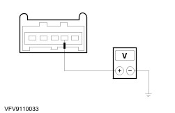
| B3: CHECK THE VOLTAGE SUPPLY TO THE LEFT-HAND STOP LAMP |
| | 1 Ignition switch in position 0. |
| | 2 Disconnect stop lamp switch from connector C62. |
| | 3 Disconnect left-hand rear lamp assembly from connector C1050(a). |
| | 4 Use a fused test cable (15 A) to bridge the stop lamp switch, connector C62, pin 1 and pin 2, wiring harness side. |
| | 5 Ignition switch in position II. |
| | 6 Measure the voltage between the left-hand rear lamp assembly: - Courier without trailer socket: connector C1050, pin 3, circuit 14S-LG38A (VT) (LHD) or 14S-LG41A (VT/BK) (RHD), wiring harness side and ground.
- Courier with trailer socket: connector C1050a, pin 3, circuit (BK/RD), wiring harness side and ground.
|
| | Does the meter display battery voltage? Yes CHECK and if necessary RENEW the rear lamp assembly. CHECK the operation of the system. No LOCATE and RECTIFY the break in the circuit between soldered connection S35 (LHD) or S36 (RHD)and the left-hand rear lamp assembly using the Wiring Diagrams. CHECK the operation of the system. |
| B4: CHECK THE VOLTAGE SUPPLY TO THE LEFT-HAND STOP LAMP |
| | 1 Ignition switch in position 0. |
| | 2 Disconnect stop lamp switch from connector C62. |
| | 3 Disconnect left-hand rear lamp assembly from connector C50(a). |
| | 4 Use a fused test cable (15 A) to bridge the stop lamp switch, connector C62, pin 1 and pin 2, wiring harness side. |
| | 5 Ignition switch in position II. |
| | 6 Measure the voltage between the left-hand rear lamp assembly: - Vehicles without trailer socket: connector C50, pin 2, circuit 14S-LG38 (VT), wiring harness side and ground.
- Vehicles with trailer socket: connector C50a, pin 2, circuit (BK/RD), wiring harness side and ground.
|
| | Does the meter display battery voltage? Yes CHECK and if necessary RENEW the rear lamp assembly. CHECK the operation of the system. No - Vehicles without trailer socket: LOCATE and RECTIFY the break in the circuit between the right-hand rear lamp assembly and the left-hand rear lamp assembly using the Wiring Diagrams. CHECK the operation of the system. - Vehicles with trailer socket: LOCATE and RECTIFY the break in the circuit between intermediate connector C49 (RHD) or C50 (LHD) and the left-hand rear lamp assembly using the Wiring Diagrams. CHECK the operation of the system. |
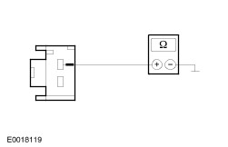
| B5: CHECK GROUND CONNECTION OF LEFT-HAND REAR LAMP ASSEMBLY |
| | 1 Ignition switch in position 0. |
| | 2 Disconnect left-hand rear lamp assembly from connector C1050(a). |
| | 3 Measure the resistance between the left-hand rear lamp assembly: - Courier without trailer socket: connector C1050, pin 2, circuit 31-LF23 (BK), wiring harness side and ground.
- Courier with trailer socket: connector C1050a, pin 2, circuit (GN), wiring harness side and ground.
|
| | Is less than 2 Ohm measured? Yes CHECK and if necessary RENEW the rear lamp assembly. CHECK the operation of the system. No LOCATE and RECTIFY the break in the circuit between the left-hand rear lamp assembly and ground G5 using the Wiring Diagrams. CHECK the operation of the system. |
| B6: CHECK GROUND CONNECTION OF LEFT-HAND REAR LAMP ASSEMBLY |
| | 1 Ignition switch in position 0. |
| | 2 Disconnect left-hand rear lamp assembly from connector C50(a). |
| | 3 Measure the resistance between the left-hand rear lamp assembly: - Vehicles without trailer socket: connector C50, pin 4, circuit 31-LF23 (BK), wiring harness side and ground.
- Vehicles with trailer socket: connector C50a, pin 4, circuit (GN), wiring harness side and ground.
|
| | Is less than 2 Ohm measured? Yes CHECK and if necessary RENEW the rear lamp assembly. CHECK the operation of the system. No LOCATE and RECTIFY the break in the circuit between the left-hand rear lamp assembly and ground G5 using the Wiring Diagrams. CHECK the operation of the system. |
| B7: DETERMINE THE FAULT CONDITION |
| | 1 Switch on the side lights. |
| | 2 Check the rear right-hand side light. |
| | Does the rear right-hand side light illuminate? Yes - RHD, except Courier and refrigerated van without trailer socket: GO to B11. - Courier and refrigerated van: GO to B8. No |
| B8: CHECK THE VOLTAGE SUPPLY TO THE RIGHT-HAND STOP LAMP |
| | 1 Ignition switch in position 0. |
| | 2 Disconnect stop lamp switch from connector C62. |
| | 3 Disconnect right-hand rear lamp assembly from connector C1049(a). |
| | 4 Use a fused test cable (15 A) to bridge the stop lamp switch, connector C62, pin 1 and pin 2, wiring harness side. |
| | 5 Ignition switch in position II. |
| | 6 Measure the voltage between the right-hand rear lamp assembly: - Courier without trailer socket: connector C1049, pin 3, circuit 14S-LG41 (VT/BK) (LHD) or 14S-LG38 (VT/BK) (RHD), wiring harness side and ground.
- Courier with trailer socket: connector C1049a, pin 3, circuit (GN), wiring harness side and ground.
|
| | Does the meter display battery voltage? Yes CHECK and if necessary RENEW the rear lamp assembly. CHECK the operation of the system. No LOCATE and RECTIFY the break in the circuit between soldered connection S35 (LHD) or S36 (RHD)and the right-hand rear lamp assembly using the Wiring Diagrams. CHECK the operation of the system. |
| B9: CHECK THE VOLTAGE SUPPLY TO THE RIGHT-HAND STOP LAMP |
| | 1 Ignition switch in position 0. |
| | 2 Disconnect stop lamp switch from connector C62. |
| | 3 Disconnect right-hand rear lamp assembly from connector C49(a). |
| | 4 Use a fused test cable (15 A) to bridge the stop lamp switch, connector C62, pin 1 and pin 2, wiring harness side. |
| | 5 Ignition switch in position II. |
| | 6 Measure the voltage between the right-hand rear lamp assembly: - Vehicles without trailer socket: connector C49, pin 4, circuit 14S-LG41 (VT/BK), wiring harness side and ground.
- Vehicles with trailer socket: connector C49a, pin 4, circuit (GN), wiring harness side and ground.
|
| | Does the meter display battery voltage? Yes CHECK and if necessary RENEW the rear lamp assembly. CHECK the operation of the system. No - Vehicles without trailer socket: LOCATE and RECTIFY the break in the circuit between the left-hand rear lamp assembly and the right-hand rear lamp assembly using the Wiring Diagrams. CHECK the operation of the system. - Vehicles with trailer socket: LOCATE and RECTIFY the break in the circuit between intermediate connector C49 (RHD) or C50 (LHD) and the right-hand rear lamp assembly using the Wiring Diagrams. CHECK the operation of the system. |
| B10: CHECK GROUND CONNECTION OF THE RIGHT-HAND REAR LAMP ASSEMBLY |
| | 1 Ignition switch in position 0. |
| | 2 Disconnect right-hand rear lamp assembly from connector C1049(a). |
| | 3 Measure the resistance between the right-hand rear lamp assembly: - Courier without trailer socket: connector C1049, pin 2, circuit 31-LF24 (BK), wiring harness side and ground.
- Courier with trailer socket: connector C1049a, pin 2, circuit (GN), wiring harness side and ground.
|
| | Is less than 2 Ohm measured? Yes CHECK and if necessary RENEW the rear lamp assembly. CHECK the operation of the system. No LOCATE and RECTIFY the break in the circuit between the right-hand rear lamp assembly and ground G3 using the Wiring Diagrams. CHECK the operation of the system. |
| B11: CHECK GROUND CONNECTION OF THE RIGHT-HAND REAR LAMP ASSEMBLY |
| | 1 Ignition switch in position 0. |
| | 2 Disconnect right-hand rear lamp assembly from connector C49(a). |
| | 3 Measure the resistance between the right-hand rear lamp assembly: - Vehicles without trailer socket: connector C49, pin 2, circuit 31-LF24 (BK), wiring harness side and ground.
- Vehicles with trailer socket: connector C49a, pin 2, (GN), wiring harness side and ground.
|
| | Is less than 2 Ohm measured? Yes CHECK and if necessary RENEW the rear lamp assembly. CHECK the operation of the system. No LOCATE and RECTIFY the break in the circuit between the right-hand rear lamp assembly and ground G3 using the Wiring Diagrams. CHECK the operation of the system. |
| B12: CHECK VOLTAGE AT THE ADDITIONAL HIGH-MOUNTED STOP LAMP |
| | 1 Ignition switch in position 0. |
| | 2 Disconnect stop lamp switch from connector C62. |
| | 3 Disconnect additional high-mounted stop lamp from connector C390. |
| | 4 Use a fused test cable (15 A) to bridge the stop lamp switch, connector C62, pin 1 and pin 2, wiring harness side. |
| | 5 Ignition switch in position II. |
| | 6 Measure the voltage between the additional high-mounted stop lamp, connector C390, pin 1, circuit 14S-LG6 (VT/YE), wiring harness side and ground. |
| | Does the meter display battery voltage? Yes No - Vehicles without ABS, except Courier and refrigerated van: LOCATE and RECTIFY the break in the circuit between the stop lamp switch and the additional high-mounted stop lamp using the Wiring Diagrams. CHECK the operation of the system. - Courier and refrigerated van: LOCATE and RECTIFY the break in the circuit between soldered connection S35 (LHD) or S36 (RHD)and the additional high-mounted stop lamp using the Wiring Diagrams. CHECK the operation of the system. - All other vehicles: LOCATE and RECTIFY the break in the circuit between soldered connection S1180 and the additional high-mounted stop lamp using the Wiring Diagrams. CHECK the operation of the system. |
| B13: CHECK GROUND CONNECTION OF ADDITIONAL HIGH-MOUNTED STOP LAMP |
| | 1 Ignition switch in position 0. |
| | 2 Measure the resistance between the additional high-mounted stop lamp, connector C390, pin 2, circuit 31-LG6 (BK), wiring harness side and ground. |
| | Is less than 2 Ohm measured? Yes CHECK and if necessary RENEW the additional high-mounted stop lamp. CHECK the operation of the system. No - Courier and refrigerated van: LOCATE and RECTIFY the break in the circuit between the additional high-mounted stop lamp and soldered connection S151 using the Wiring Diagrams. CHECK the operation of the system. - All other vehicles with anti-theft warning system: LOCATE and RECTIFY the break in the circuit between the additional high-mounted stop lamp and soldered connection S121 (up to 09/2000) or S1140 (from 09/2002) using the Wiring Diagrams. CHECK the operation of the system. - All other vehicles without anti-theft warning system: LOCATE and RECTIFY the break in the circuit between the additional high-mounted stop lamp and ground G12 (up to 09/2000) or G21 (from 09/2002) using the Wiring Diagrams. CHECK the operation of the system. |