| PINPOINT TEST A : ELECTRIC BOOSTER HEATER INOPERATIVE / PARTLY INOPERATIVE |
NOTE:Before checking, make certain that all the switch-on conditions described in the operational description are satisfied. |
| TEST CONDITIONS | DETAILS/RESULTS/ACTIONS |
| A1: DETERMINE VEHICLE EQUIPMENT LEVEL |
| | 1 Determine vehicle equipment level. |
| | Is the vehicle equipped with 1.4L diesel engine without automatic clutch and gearshift actuation? Yes - Vehicle equipped with 1.4L diesel engine without automatic clutch and gearshift actuation: GO to A2. No - Vehicle with 1.6L diesel engine or 1.4L diesel engine with automatic clutch and gearshift actuation: GO to A18. |
| A2: CHECK THE OPERATION OF THE ELECTRIC BOOSTER HEATER |
| | 1 Ignition switch in position III. 2 Run the engine at idle speed. |
| | 3 Measure the current in circuit 31-FC9 (BK) at the electric booster heater using a clip-on ammeter. |
| | 4 Set the blower switch to level 1 and the temperature control to warm. |
| | Is a current of more than 10 A measured? Yes No |
| A3: CHECK THE LEVEL 1 CIRCUIT OF THE ELECTRIC BOOSTER HEATER |
| | 1 Measure the current in circuit 20S-FC9 (PK/OG) at the electric booster heater using a clip-on ammeter. |
| | Is a current of more than 10 A measured? Yes No |
| A4: CHECK FUSE F13 |
| | 1 Ignition switch in position 0. |
| | 2 CHECK Fuse F13 (CJB). |
| | Is the fuse OK? Yes No Install a new fuse F13 (20 A). CHECK operation of system. If the fuse blows again, LOCATE and REPAIR the short using the Wiring Diagrams. |
| A5: TEST VOLTAGE AT FUSE F13 |
| | 1 Connect Fuse F13 (CJB). |
| | 2 Ignition switch in position II. |
| | 3 Measure the voltage between fuse F13 (20 A) and ground. |
| | Does the meter display battery voltage? Yes No REPAIR the voltage supply to fuse F13 with the aid of the Wiring Diagrams. CHECK the operation of the system. |
| A6: TEST CONTROL VOLTAGE AT PTC HEATER RELAY 1 |
| | 1 Ignition switch in position 0. |
| | 2 Disconnect PTC heater relay 1 from socket C730 (relay box, engine compartment). |
| | 3 Ignition switch in position II. |
| | 4 Measure the voltage between PTC heater relay 1, socket C730, pin 1, circuit 15S-FC16 (GN/OG) wiring harness side and ground. |
| | Does the meter display battery voltage? Yes No LOCATE and REPAIR the break in circuit 15S-FC16 (GN/OG) between fuse F13 and soldered connection S108 using the Wiring Diagrams. CHECK the operation of the system. |
| A7: CHECK THE ELECTRIC BOOSTER HEATER GROUND CONNECTION |
| | 1 Ignition switch in position 0. |
| | 2 Measure the resistance between the electric booster heater, connector C757, circuit 31-FC9 (BK) and ground. |
| | Is a resistance of less than 0,5 Ohm registered? Yes No LOCATE and REPAIR the break in circuit 31-FC9 (BK) between the electric booster heater and ground connection G28 using the Wiring Diagrams. CHECK the operation of the system. |
| A8: CHECK THE SIGNAL FROM THE INTAKE AIR TEMPERATURE SENSOR |
NOTE:The intake air temperature sensor is integral with the mass air flow sensor (engine management). |
| | 1 Connect the diagnostic tool. |
| | 2 Select vehicle and read out the intake air temperature sensor data in the PCM datalogger. |
| | Is the temperature value shown OK, i.e. is the temperature value shown plausible? Yes No For further information, refer to
REFER to: Electronic Engine Controls (303-14 Electronic Engine Controls, Diagnosis and Testing).
|
| A9: CHECK THE ELECTRIC BOOSTER HEATER |
NOTE:If the powertrain control module (PCM) is changed, the new one must be programmed. For this purpose, the vehicle-specific data is read out of the module to be replaced using WDS and is transferred to the new module. |
NOTE:Before reading out the vehicle-specific data, remake all the electrical connections in the vehicle, so that communication between the module and WDS is ensured. |
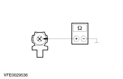
| | 1 Measure the resistance at the electric booster heater, between connector C755 and connector C757. |
| | Is a resistance of less than 1,5 Ohm registered? Yes TEST the powertrain control module (PCM) and RENEW as necessary. CHECK the operation of the system. No RENEW the electric booster heater. CHECK the operation of the system. |
| A10: CHECK FUSE FC (VEHICLES WITH EUROPEAN ON-BOARD DIAGNOSIS (EOBD): FUSE FB) |
| | 1 Ignition switch in position 0. |
| | 2 CHECK Fuse FC (vehicles with EOBD: fuse FB) (BJB). |
| | Is the fuse OK? Yes No RENEW fuse FC (vehicles with EOBD: fuse FB) (60A). CHECK the operation of the system. If the fuse blows again, LOCATE and RECTIFY the short to ground using the wiring diagrams. |
| A11: CHECK VOLTAGE AT FUSE FC (VEHICLES WITH EOBD: FUSE FB) |
| | 1 Connect Fuse FC (vehicles with EOBD: fuse FB). |
| | 2 Measure the voltage between fuse FC (vehicles with EOBD: fuse FB) (60A) and ground. |
| | Does the meter display battery voltage? Yes No REPAIR the voltage supply to fuse FC (vehicles with EOBD: fuse FB) using the Wiring Diagrams. CHECK the operation of the system. |
| A12: TEST THE CONTROL VOLTAGE AT PTC HEATER RELAY 1 |
| | 1 Disconnect PTC heater relay 1 from socket C730 (relay box, engine compartment). |
| | 2 Ignition switch in position II. |
| | 3 Measure the voltage between PTC heater relay 1, socket C730, pin 1, circuit 15S-FC16 (GN/OG) wiring harness side and ground. |
| | Does the meter display battery voltage? Yes No LOCATE and REPAIR the break in circuit 15S-FC16 (GN/OG) between PTC heating relay 1 and soldered connection S108 using the Wiring Diagrams. CHECK the operation of the system. |
| A13: TEST THE VOLTAGE AT PTC HEATER RELAY 1 |
| | 1 Ignition switch in position 0. |
| | 2 Measure the voltage between PTC heater relay 1, socket C730, pin 3, circuit 30-FC17 (RD), wiring harness side and ground. |
| | Does the meter display battery voltage? Yes No LOCATE and REPAIR break in circuit 30-FC17 (RD) between PTC heating relay 1 and fuse FC (vehicles with EOBD: soldered connection S125) using the Wiring Diagrams. CHECK the operation of the system. |
| A14: TEST FOR BREAK IN THE CIRCUIT BETWEEN PTC HEATER RELAY 1 AND THE ELECTRIC BOOSTER HEATER |
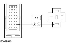
| | 1 Measure resistance between PTC heater relay 1, socket C730, pin 5, circuit 20S-FC9 (PK/OG), wiring harness side and electric booster heater, connector C755, circuit 20S-FC9 (PK/OG). |
| | Is a resistance of less than 0,5 Ohm registered? Yes No LOCATE and REPAIR the break in circuit 20S-FC9 (PK/OG) between PTC heating relay 1 and electric booster heater using the Wiring Diagrams. CHECK the operation of the system. |
| A15: CHECK THE ELECTRIC BOOSTER HEATER |
| | 1 Measure the resistance at the electric booster heater, between connector C755, circuit 20S-FC9 (PK/OG) and connector C757, circuit 31-FC9 (BK). |
| | Is a resistance of less than 1,5 Ohm registered? Yes No RENEW the electric booster heater. CHECK the operation of the system. |
| A16: CHECK PCM |
NOTE:If the powertrain control module (PCM) is changed, the new one must be programmed. For this purpose, the vehicle-specific data is read out of the module to be replaced using WDS and is transferred to the new module. |
NOTE:Before reading out the vehicle-specific data, remake all the electrical connections in the vehicle, so that communication between the module and WDS is ensured. |
| | 1 Connect PTC heater relay 1 at socket C730. |
| | 2 Disconnect Connector C370 (vehicles with electronic exhaust gas recirculation valve (EGR): C375) from PCM. |
| | 3 Use a fused test cable (1 A) at the PCM to bridge between connector C370 (vehicles with electronic exhaust gas recirculation valve (EGR): C375), pin B1, circuit 91S-FC 16 (BK/RD), wiring harness side and ground. |
| | 4 Ignition switch in position II. |
| | 5 Set the blower switch to level 1 and the temperature control to warm. |
| | Is the electric booster heater operating? Yes TEST the PCM and RENEW as necessary. CHECK the operation of the system. No |
| A17: CHECK FOR BREAKS IN THE CIRCUIT BETWEEN THE PCM AND PTC HEATER RELAY 1 |
| | 1 Ignition switch in position 0. |
| | 2 Disconnect PTC heater relay 1 from socket C730. |
| | 3 Measure the resistance between the PTC heater relay 1, socket C730, pin 2, circuit 91S-FC16 (BK/RD), wiring harness side and the PCM, connector C370 (vehicles with electronic exhaust gas recirculation valve (EGR): C375), pin B1, circuit 91S-FC16 (BK/RD), wiring harness side. |
| | Is a resistance of less than 2 Ohm registered? Yes RENEW PTC heater relay 1. CHECK the operation of the system. No LOCATE and REPAIR the break in circuit 91S-FC16 (BK/RD) between the PCM and PTC heater relay 1 with the aid of the Wiring Diagrams. CHECK the operation of the system. |
| A18: TEST FUSE FA |
| | 1 Ignition switch in position 0. |
| | 2 CHECK Fuse FA (BJB). |
| | Is the fuse OK? Yes No RENEW fuse FA (80 A). CHECK system operates correctly If the fuse blows again, LOCATE and RECTIFY the short to ground using the wiring diagrams. |
| A19: TEST VOLTAGE AT FUSE FA |
| | 1 Connect Fuse FA. |
| | 2 Measure the voltage between fuse FA (80A) and ground. |
| | Does the meter display battery voltage? Yes No REPAIR the voltage supply to fuse FA with the aid of the Wiring Diagrams. CHECK system operates correctly |
| A20: TEST CONTROL VOLTAGE AT PTC HEATER RELAY 2 |
| | 1 Disconnect PTC heater relay 2 from socket C731 (relay box, engine compartment). |
| | 2 Ignition switch in position II. |
| | 3 Measure the voltage between PTC heater relay 2, socket C731, pin 1, circuit 15S-FC18 (GN/WH), wiring harness side and ground. |
| | Does the meter display battery voltage? Yes No LOCATE and REPAIR the break in circuit 15S-FC18 (GN/WH) between PTC heating relay 2 and soldered connection S108 (vehicles with diesel engine: soldered connection S112) using the Wiring Diagrams. CHECK system operates correctly |
| A21: TEST VOLTAGE AT PTC HEATER RELAY 2 |
| | 1 Ignition switch in position 0. |
| | 2 Measure the voltage between PTC heater relay 2, socket C731, pin 3, circuit 30-FC19 (RD), wiring harness side and ground. |
| | Does the meter display battery voltage? Yes No LOCATE and REPAIR the break in circuit 30-FC19 (RD) between PTC heater relay 2 and fuse FA with the aid of the Wiring Diagrams. CHECK system operates correctly |
| A22: TEST FOR BREAK IN THE CIRCUIT BETWEEN PTC HEATER RELAY 2 AND THE ELECTRIC BOOSTER HEATER |
| | 1 Measure resistance between PTC heater relay 2, socket C731, pin 5, circuit 20S-FC15 (PK/WH), wiring harness side and electric booster heater, connector C756, circuit 20S-FC15 (PK/WH). |
| | Is a resistance of less than 0,5 Ohm registered? Yes No LOCATE and REPAIR the break in circuit 20S-FC15 (PK/WH) between PTC heating relay 2 and electric booster heater using the Wiring Diagrams. CHECK system operates correctly |
| A23: CHECK THE ELECTRIC BOOSTER HEATER |
| | 1 Measure the resistance at the electric booster heater, between connector C756, circuit 20S-FC15 (PK/WH) and connector C757, circuit 31-FC9 (BK). |
| | Is a resistance of less than 1 Ohm registered? Yes No RENEW the electric booster heater. CHECK system operates correctly |
| A24: CHECK PCM |
NOTE:If the powertrain control module (PCM) is changed, the new one must be programmed. For this purpose, the vehicle-specific data is read out of the module to be replaced using WDS and is transferred to the new module. |
NOTE:Before reading out the vehicle-specific data, remake all the electrical connections in the vehicle, so that communication between the module and WDS is ensured. |
| | 1 Connect PTC heater relay 2 at socket C731. |
| | 2 Disconnect Connector C370 (vehicles with electronic exhaust gas recirculation valve (EGR): C375, vehicles with 1.6L diesel engine: C384) from PCM. |
| | 3 Use a fused test cable (1 A) at the PCM to bridge between connector C370 (vehicles with electronic exhaust gas recirculation valve (EGR): C375, vehicles with 1.6L diesel engine: C384), pin C1, circuit 91S-FC18 (BK/WH), wiring harness side and ground. |
| | 4 Ignition switch in position II. |
| | 5 Set the blower switch to level 1 and the temperature control to warm. |
| | Is the electric booster heater operating? Yes TEST the PCM and RENEW as necessary. CHECK the operation of the system. No |
| A25: TEST FOR BREAKS IN THE CIRCUIT BETWEEN THE PCM AND PTC HEATER RELAY 2 |
| | 1 Ignition switch in position 0. |
| | 2 Disconnect PTC heater relay 2 from socket C731. |
| | 3 Measure the resistance between the PTC heater relay 2, socket C731, pin 2, circuit 91S-FC18 (BK/WH), wiring harness side and the PCM, connector C370 (vehicles with electronic exhaust gas recirculation valve (EGR): C375, vehicles with 1.6L diesel engine: C384), pin C1, circuit 91S-FC18 (BK/WH), wiring harness side. |
| | Is a resistance of less than 2 Ohm registered? Yes RENEW PTC heater relay 2. CHECK the operation of the system. No LOCATE and REPAIR the break in circuit 91S-FC18 (BK/WH) between the PCM and PTC heater relay 2 with the aid of the Wiring Diagrams. CHECK the operation of the system. |