| PINPOINT TEST A : COOLANT ADDITIONAL ELECTRIC HEATER INOPERATIVE / PARTLY INOPERATIVE |
NOTE:The coolant additional electric heater only operates when the engine is running (signal D+ from generator) and there is enough generator capacity. The coolant temperature must not exceed 75°C and the ambient temperature must be below 5°C. |
| TEST CONDITIONS | DETAILS/RESULTS/ACTIONS |
| A1: DETERMINE THE CONDITIONS UNDER WHICH THE FAULT OCCURS |
| | 1 Check the operation of the coolant additional electric heater. |
| | Are levels 1 and 2 of the coolant additional electric heater inoperative? Yes No |
| A2: CHECK THE CONTROL VOLTAGE AT THE GLOW PLUG HEATING RELAY, STAGE 1 |
| | 1 Ignition switch in position 0. |
| | 2 Disconnect Glow plug heating relay, stage 1 C1002 (BJB). |
| | 3 Ignition switch in position II. |
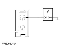
| | 4 Measure the voltage between the glow plug heating relay, stage 1, connector C1002, pin 1, circuit 15-RH23 (GN/RD), wiring harness side and ground. |
| | Does the meter display battery voltage? Yes No LOCATE and RECTIFY the break in circuit 15-RH10 (GN/RD) between power hold relay and soldered connection S117 with the aid of the Wiring Diagrams. CHECK system operates correctly |
| A3: TEST THE SIGNAL FROM THE INTAKE AIR TEMPERATURE SENSOR |
NOTE:The intake air temperature sensor is integrated in the mass air flow sensor (engine management). |
| | 1 Ignition switch in position 0. |
| | 2 Connect the diagnostic tool. |
| | 3 Ignition switch in position II. |
| | 4 Test the intake air temperature signal using the WDS. |
| | Is the intake air temperature signal OK, i.e. is the indicated temperature value plausible? Yes No |
| A4: CHECK THE GROUND CONNECTION OF THE COOLANT ADDITIONAL ELECTRIC HEATER |
| | 1 Ignition switch in position 0. |
| | 2 Measure the resistance between the coolant additional electric heater, connector C965, circuit 15-RD22 (GN/RD) and ground. |
| | Is a resistance of less than 1,1 Ohm measured? Yes CHECK the powertrain control module (PCM) and RENEW as necessary. CHECK system operates correctly No CHECK the ground connection of the coolant additional electric heater, if necessary CLEAN the threaded connection(s) on the bulkhead. CHECK system operates correctly |
| A5: CHECK FUSE F24 |
| | 1 Ignition switch in position 0. |
| | 2 CHECK Fuse F24 (BJB). |
| | Is the fuse OK? Yes No RENEW fuse F24 (30 A). CHECK system operates correctly If the fuse blows again, LOCATE and RECTIFY the short to ground with the aid of the Wiring Diagrams. |
| A6: TEST VOLTAGE AT FUSE F24 |
| | 1 Connect Fuse F24 (BJB). |
| | 2 Test voltage between fuse F24 (30 A) and ground. |
| | Does the meter display battery voltage? Yes No REPAIR the voltage supply to fuse F24 with the aid of the Wiring Diagrams. CHECK system operates correctly |
| A7: CHECK THE CONTROL VOLTAGE AT THE GLOW PLUG HEATING RELAY, STAGE 1 |
| | 1 Disconnect Glow plug heating relay, stage 1 C1002 (BJB). |
| | 2 Ignition switch in position II. |
| | 3 Measure the voltage between the glow plug heating relay, stage 1, connector C1002, pin 1, circuit 15-RH23 (GN/RD), wiring harness side and ground. |
| | Does the meter display battery voltage? Yes No LOCATE and RECTIFY the break in circuit 15-RH23 (GN/RD) between glow plug heating relay, stage 1 and soldered connection S117 with the aid of the Wiring Diagrams. CHECK system operates correctly |
| A8: CHECK THE VOLTAGE AT THE GLOW PLUG HEATING RELAY, STAGE 1 |
| | 1 Ignition switch in position 0. |
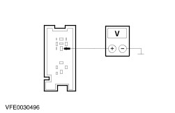
| | 2 Measure the voltage between the glow plug heating relay, stage 1, connector C1002, pin 3, circuit 30-RH24 (RD), wiring harness side and ground. |
| | Does the meter display battery voltage? Yes No LOCATE and RECTIFY the break in circuit 30-RH24 (RD) between glow plug heating relay, stage 1 and fuse F24 with the aid of the Wiring Diagrams. CHECK system operates correctly |
| A9: CHECK THE CIRCUIT BETWEEN GLOW PLUG HEATING RELAY, STAGE 1 AND THE COOLANT ADDITIONAL ELECTRIC HEATER FOR OPEN CIRCUIT. |
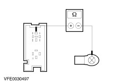
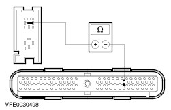
| | 1 Measure the resistance between glow plug heating relay, stage 1, socket C1002, pin 5, wiring harness side and coolant additional electric heater, connector C965, circuit 15-RD22 (GN/RD). |
| | Is a resistance of less than 0,5 Ohms measured? Yes No LOCATE and REPAIR the break in the circuit between the glow plug heating relay, stage 1 and the coolant additional electric heater with the aid of the Wiring Diagrams. CHECK system operates correctly |
| A10: CHECK THE COOLANT ADDITIONAL ELECTRIC HEATER |
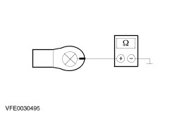
| | 1 Measure the resistance between the coolant additional electric heater, connector C965, circuit 15-RD22 (GN/RD) and ground. |
| | Is a resistance of less than 1,1 Ohm registered? Yes No RENEW the coolant additional electric heater. CHECK system operates correctly |
| A11: CHECK THE GLOW PLUG HEATING RELAY, STAGE 1 |
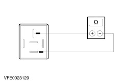
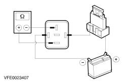
| | 1 Test the glow plug heating relay, stage 1, according to the component tests at the end of this section. |
| | Is the glow plug heating relay, stage 1 OK? Yes No RENEW the glow plug heating relay, stage 1. CHECK system operates correctly |
| A12: TEST FOR BREAKS IN THE CIRCUIT BETWEEN THE PCM AND THE GLOW PLUG HEATING RELAY STAGE 1 |
| | 1 Disconnect PCM C415. |
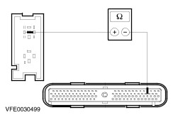
| | 2 Measure the resistance between glow plug heating relay, stage 1, socket C1002, pin 2, wiring harness side and PCM, connector C415, pin 98, circuit 31S-RH23 (BK/OG), wiring harness side. |
| | Is a resistance of less than 2 Ohm registered? Yes TEST the PCM and RENEW it if necessary. CHECK the operation of the system. No LOCATE and REPAIR the break in the circuit between PCM and glow plug heating relay stage 1 with the aid of the Wiring Diagrams. CHECK the operation of the system. |
| A13: TEST FOR BREAKS IN THE CIRCUIT BETWEEN THE PCM AND THE GLOW PLUG HEATING RELAY STAGE 1 |
| | 1 Disconnect PCM 414. |
| | 2 Measure the resistance between glow plug heating relay, stage 1, socket C1002, pin 2, wiring harness side and PCM, connector C414, pin 61, circuit 31S-RH23 (BK/OG), wiring harness side. |
| | Is a resistance of less than 2 Ohm registered? Yes TEST the PCM and RENEW it if necessary. CHECK the operation of the system. No LOCATE and REPAIR the break in the circuit between PCM and glow plug heating relay stage 1 with the aid of the Wiring Diagrams. CHECK system operates correctly |
| A14: CHECK FUSE F3 |
| | 1 Ignition switch in position 0. |
| | 2 CHECK Fuse F3 (BJB). |
| | Is the fuse OK? Yes No RENEW fuse F3 (40 A). CHECK system operates correctly If the fuse blows again, LOCATE and RECTIFY the short to ground with the aid of the Wiring Diagrams. |
| A15: TEST VOLTAGE AT FUSE F3 |
| | 1 Connect Fuse F3 (BJB). |
| | 2 Test voltage between fuse F3 (40 A) and ground. |
| | Does the meter display battery voltage? Yes No REPAIR the voltage supply to fuse F3 with the aid of the Wiring Diagrams. CHECK system operates correctly |
| A16: CHECK THE CONTROL VOLTAGE AT THE GLOW PLUG HEATING RELAY, STAGE 2 |
| | 1 Disconnect Glow plug heating relay, stage 2 C1010 (BJB). |
| | 2 Ignition switch in position II. |
| | 3 Measure the voltage between the glow plug heating relay, stage 2, connector C1010, pin 1, circuit 15-RH25 (GN/BK), wiring harness side and ground. |
| | Does the meter display battery voltage? Yes No LOCATE and RECTIFY the break in circuit 15-RH25 (GN/BK) between glow plug heating relay, stage 2 and soldered connection S117 with the aid of the Wiring Diagrams. CHECK system operates correctly |
| A17: CHECK THE VOLTAGE AT THE GLOW PLUG HEATING RELAY, STAGE 2 |
| | 1 Ignition switch in position 0. |
| | 2 Measure the voltage between the glow plug heating relay, stage 2, connector C1010, pin 3, circuit 30-RH26 (RD), wiring harness side and ground. |
| | Does the meter display battery voltage? Yes No LOCATE and RECTIFY the break in circuit 30-RH26 (RD) between glow plug heating relay, stage 2 and fuse F3 with the aid of the Wiring Diagrams. CHECK system operates correctly |
| A18: CHECK THE CIRCUIT BETWEEN GLOW PLUG HEATING RELAY, STAGE 2 AND THE COOLANT ADDITIONAL ELECTRIC HEATER FOR OPEN CIRCUIT. |
| | 1 Measure resistance between glow plug heating relay, stage 2, socket C1010, pin 5, wiring harness side and coolant additional electric heater, connector C967, wiring harness side. |
| | Is a resistance of less than 0,5 Ohm registered? Yes No LOCATE and REPAIR the break in the circuit between the glow plug heating relay, stage 2 and the coolant additional electric heater with the aid of the Wiring Diagrams. CHECK system operates correctly |
| A19: CHECK THE COOLANT ADDITIONAL ELECTRIC HEATER |
| | 1 Measure the resistance between the coolant additional electric heater, connector C966, circuit 15-RD23 (GN/BK) and ground. |
| | Is a resistance of less than 0,8 Ohm registered? Yes No RENEW the coolant additional electric heater. CHECK system operates correctly |
| A20: CHECK THE GLOW PLUG HEATING RELAY, STAGE 2 |
| | 1 Test the glow plug heating relay, stage 2, according to the component tests at the end of this section. |
| | Is the glow plug heating relay, stage 2 OK? Yes No RENEW the glow plug heating relay, stage 2. CHECK the operation of the system. |
| A21: TEST FOR BREAKS IN THE CIRCUIT BETWEEN THE PCM AND THE GLOW PLUG HEATING RELAY STAGE 2 |
| | 1 Disconnect PCM C415. |
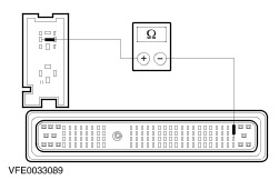
| | 2 Measure the resistance between glow plug heating relay, stage 2, socket C1010, pin 2, wiring harness side and PCM, connector C415, pin 75, circuit 31S-RH25 (BK/GN), wiring harness side. |
| | Is a resistance of less than 2 Ohm registered? Yes TEST the PCM and RENEW it if necessary. CHECK the operation of the system. No LOCATE and REPAIR the break in the circuit between PCM and glow plug heating relay stage 2 with the aid of the Wiring Diagrams. CHECK the operation of the system. |
| A22: TEST FOR BREAKS IN THE CIRCUIT BETWEEN THE PCM AND THE GLOW PLUG HEATING RELAY STAGE 2 |
| | 1 Disconnect PCM C414. |
| | 2 Measure the resistance between glow plug heating relay, stage 2, socket C1010, pin 2, wiring harness side and PCM, connector C414, pin 62, circuit 31S-RH25 (BK/GN), wiring harness side. |
| | Is a resistance of less than 2 Ohm registered? Yes TEST the PCM and RENEW it if necessary. CHECK the operation of the system. No LOCATE and REPAIR the break in the circuit between PCM and glow plug heating relay stage 2 with the aid of the Wiring Diagrams. CHECK the operation of the system. |