| PINPOINT TEST A : FUEL-FIRED BOOSTER HEATER INOPERATIVE |
| TEST CONDITIONS | DETAILS/RESULTS/ACTIONS |
| A1: CHECK FUSE F23 |
| | 1 Ignition switch in position 0. |
| | 2 CHECK Fuse F23 (BJB). |
| | Is the fuse OK? Yes No RENEW fuse F23 (20 A). CHECK that the system operates correctly. If the fuse blows again, LOCATE and RECTIFY the short to ground with the aid of the Wiring Diagrams. |
| A2: CHECK THE VOLTAGE AT FUSE F23 |
| | 1 Connect Fuse F23 (BJB). |
| | 2 Measure the voltage between fuse F23 (20 A) and ground. |
| | Does the meter display battery voltage? Yes No REPAIR the voltage supply to fuse F23 with the aid of the Wiring Diagrams. CHECK that the system operates correctly. |
| A3: CHECK FUSE F28 |
| | 1 CHECK Fuse F28 (BJB). |
| | Is the fuse OK? Yes No RENEW fuse F28 (10 A). CHECK that the system operates correctly. If the fuse blows again, LOCATE and RECTIFY the short to ground with the aid of the Wiring Diagrams. |
| A4: CHECK THE VOLTAGE AT FUSE F28 |
| | 1 Connect Fuse F28 (BJB). |
| | 2 Ignition switch in position II. |
| | 3 Measure the voltage between fuse F28 (10 A) and ground. |
| | Does the meter display battery voltage? Yes No REPAIR the voltage supply to fuse F28 with the aid of the Wiring Diagrams. CHECK that the system operates correctly. |
| A5: CHECK THE VOLTAGE AT THE BOOSTER HEATER |
| | 1 Ignition switch in position 0. |
| | 2 Disconnect Booster heater C878. |
| | 3 Measure the voltage between the booster heater, connector C878, pin 1, circuit 30-RD18 (RD), wiring harness side and ground. |
| | Does the meter display battery voltage? Yes No LOCATE and RECTIFY the break in the circuit between the booster heater and fuse F23 with the aid of the Wiring Diagrams. CHECK that the system operates correctly. |
| A6: CHECK THE VOLTAGE AT THE BOOSTER HEATER |
| | 1 Ignition switch in position II. |
| | 2 Measure the voltage between the booster heater, connector C878, pin 4, circuit 15-RD18 (GN/RD), wiring harness side and ground. |
| | Does the meter display battery voltage? Yes No LOCATE and RECTIFY the break in the circuit between the booster heater and soldered connection S117 with the aid of the Wiring Diagrams. CHECK that the system operates correctly. |
| A7: CHECK THE CONTROL VOLTAGE AT THE BOOSTER HEATER |
NOTE:Use appropriate means to cool down the ambient temperature sensor to at least 5°C. |
| | 1 Ignition switch in position III. |
| | 2 Measure the voltage between the booster heater, connector C878, pin 5, circuit 64S-RD18 (BU/WH), wiring harness side and ground. |
| | Does the meter display battery voltage? Yes No |
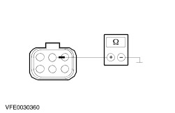
| A8: CHECK THE GROUND CONNECTION OF THE BOOSTER HEATER |
| | 1 Ignition switch in position 0. |
| | 2 Measure the resistance between the booster heater, connector C878, pin 2, circuit 31-RD18 (BK), wiring harness side and ground. |
| | Is a resistance of less than 2 Ohm registered? Yes CHECK and if necessary RENEW the booster heater. CHECK that the system operates correctly. No LOCATE and RECTIFY the break in the circuit between the booster heater and ground connection G37 with the aid of the Wiring Diagrams. CHECK that the system operates correctly. |
| A9: CHECK THE VOLTAGE AT THE AMBIENT TEMPERATURE SENSOR |
| | 1 Ignition switch in position 0. |
| | 2 Disconnect Ambient temperature sensor (C875). |
| | 3 Ignition switch in position III. |
| | 4 Measure the voltage between the ambient temperature sensor, connector C875, pin 1, circuit 64-RD18 (BU/WH), wiring harness side and ground. |
| | Does the meter display battery voltage? Yes No |
| A10: CHECK THE CIRCUIT BETWEEN THE AMBIENT TEMPERATURE SENSOR AND THE BOOSTER HEATER FOR OPEN CIRCUIT |
| | 1 Ignition switch in position 0. |
| | 2 Measure the resistance between the ambient temperature sensor, connector C875, pin 2, circuit 64S-RD18 (BU/WH), wiring harness side and the booster heater, connector 878, pin 5, circuit 64S-RD18 (BU/WH), wiring harness side. |
| | Is a resistance of less than 2 Ohm registered? Yes RENEW the ambient temperature sensor. CHECK that the system operates correctly. No LOCATE and RECTIFY the break in circuit 64S-RD18 (BU/WH) between the ambient temperature sensor and the booster heater with the aid of the Wiring Diagrams. CHECK that the system operates correctly. |
| A11: CHECK THE VOLTAGE AT THE ENGINE RUN RELAY |
| | 1 Ignition switch in position 0. |
| | 2 Disconnect Engine run relay C1013 (BJB). |
| | 3 Ignition switch in position II. |
| | 4 Measure the voltage between the engine run relay, socket C1013, pin 3, circuit 15-PA20 (GN/OG), wiring harness side and ground. |
| | Does the meter display battery voltage? Yes No LOCATE and RECTIFY the open circuit in circuit 15-PA20 (GN/OG) between the engine run relay and fuse F28 with the aid of the Wiring Diagrams. CHECK that the system operates correctly. |
| A12: CHECK THE CONTROL VOLTAGE AT THE ENGINE RUN RELAY |
| | 1 Measure the voltage between the engine run relay, socket C1013, pin 1, circuit 15-PA19 (GN/BK), wiring harness side and ground. |
| | Does the meter display battery voltage? Yes No LOCATE and RECTIFY the break in the circuit between the engine run relay and soldered connection S117 with the aid of the Wiring Diagrams. CHECK that the system operates correctly. |
| A13: CHECK THE GROUND CONNECTION OF THE ENGINE RUN RELAY |
CAUTION:It is imperative that a test lamp with a nominal voltage of 12 V and a nominal power rating of 1.2 W is used during the following test. Otherwise the PCM could be damaged, or the test could deliver incorrect results. |
NOTE:Make sure that the generator is working correctly before performing the following measurement. |
| | 1 Ignition switch in position III. |
| | 2 Use a test lamp (12 V, 1.2 W) to check the voltage at the engine run relay, socket C1013, between pin 1 and pin 2, wiring harness side. |
| | Does the test lamp light up? Yes No |
| A14: CHECK THE CIRCUIT BETWEEN THE ENGINE RUN RELAY AND THE AMBIENT TEMPERATURE SENSOR FOR OPEN CIRCUIT. |
| | 1 Ignition switch in position 0. |
| | 2 Measure the resistance between the engine run relay, socket C1013, pin 5, circuit 64-PA20 (BU/YE), wiring harness side and the ambient temperature sensor, connector C875, pin 1, circuit 64-RD18 (BU/WH), wiring harness side. |
| | Is a resistance of less than 2 Ohm measured? Yes RENEW the engine run relay. CHECK that the system operates correctly. No LOCATE and RECTIFY the break in the circuit between the engine run relay and the ambient temperature sensor with the aid of the Wiring Diagrams. CHECK that the system operates correctly. |
| A15: CHECK THE CIRCUIT BETWEEN THE ENGINE RUN RELAY AND THE POWERTRAIN CONTROL MODULE (PCM) FOR OPEN CIRCUIT |
| | 1 Ignition switch in position 0. |
| | 2 Disconnect PCM C415. |
| | 3 Measure the resistance between the engine run relay, socket C1013, pin 2, wiring harness side and the PCM, connector C415, pin 6, circuit 31S-PA19 (BK/GN), wiring harness side. |
| | Is a resistance of less than 2 Ohm registered? Yes CHECK and if necessary RENEW the PCM. CHECK the operation of the system. No LOCATE and RECTIFY the break in the circuit between the engine run relay and the PCM with the aid of the Wiring Diagrams. CHECK the operation of the system. |
| A16: CHECK THE CIRCUIT BETWEEN THE ENGINE RUN RELAY AND THE POWERTRAIN CONTROL MODULE (PCM) FOR OPEN CIRCUIT |
| | 1 Ignition switch in position 0. |
| | 2 Disconnect PCM C414. |
| | 3 Measure the resistance between the engine run relay, socket C1013, pin 2, wiring harness side and the PCM, connector C414, pin 23, circuit 31S-PA19 (BK/GN), wiring harness side. |
| | Is a resistance of less than 2 Ohm registered? Yes CHECK and if necessary RENEW the PCM. CHECK the operation of the system. No LOCATE and RECTIFY the break in the circuit between the engine run relay and the PCM with the aid of the Wiring Diagrams. CHECK the operation of the system. |