| Removal and Installation Electric hand drill Drill bit 5 mm Hole cutter 29 mm Hole cutter 35 mm Hole cutter 70 mm Removal All vehicles | | -
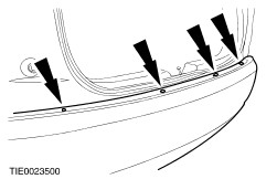
Remove the upper pushpin retainers. | | | -
Detach the bumper cover from the fender splash shield on both sides. | | | -
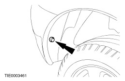
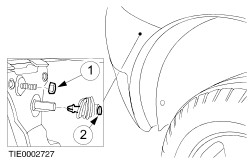
Detach the bumper cover from the fender on both sides. - Remove the retaining nut.
- Remove the clip.
| | | -
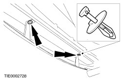
Remove the lower pushpin retainers. | | | -
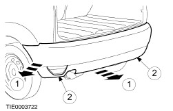
CAUTION:The bumper cover ends must be pulled away from the fenders to prevent damage to the paintwork. NOTE:With the aid of another technician, support the bumper cover. Detach the bumper cover from the fenders. - Detach the clips.
- Disconnect the fog lamp and reversing lamp electrical connectors (if equipped).
| Vehicles with parking aid built up to 10/2001 | | -
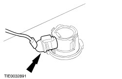
NOTE:With the aid of another technician, support the bumper cover. Remove the parking aid sensors. - Disconnect the electrical connector.
- Depress the tangs.
- Push the sensor through the bumper cover.
| | | -
Detach the bumper padding. | | | -
NOTE:Bumper padding shown removed for clarity. Remove the bumper padding. - Detach the parking aid sensor wiring harness from the bumper padding.
| Vehicles with parking aid built 10/2001 onwards | | -
NOTE:If not installing new sensor covers or sensor housings, remove them from the bumper cover. NOTE:With the aid of another technician, support the bumper cover. Remove the parking aid sensors. - Disconnect the electrical connector.
- Depress the tangs.
- Remove the sensor.
| All vehicles Installation Vehicles with parking aid built up to 10/2001 | | -
NOTE:Do not fully tighten the retaining nuts at this stage. Install the bumper padding. | | | -
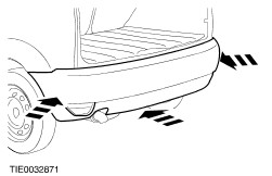
Install the bumper cover. | | | -
NOTE:Use the templates supplied with the manufacturers instructions. NOTE:Templates shown for reference. Cut out the parking aid sensor position templates. - Left-hand side outer template.
- Left-hand side inner template.
- Right-hand side inner template.
- Right-hand side outer template.
| | | -
NOTE:Bumper cover shown removed for clarity. NOTE:Note the position of the upper and lower edges of the templates. NOTE:Positional tolerance ± 5 mm. Using suitable tape, secure the parking aid sensor templates to the bumper cover as shown. - Left-hand side outer template.
- Left-hand side inner template.
- Right-hand side inner template.
- Right-hand side outer template.
| | | -
Using a suitable center punch and hammer, mark the position of the parking aid sensor location holes. | | | -
NOTE:Bumper cover shown removed for clarity. - Left-hand side outer hole.
- Left-hand side inner hole.
- Right-hand side inner hole.
- Right-hand side outer hole.
| | | -
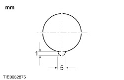
Using a suitable round file, cut the parking aid sensor cover location grooves in the bumper cover as shown (+0.5 mm, –0.0 mm). | | | -
CAUTION:The bumper cover ends must be pulled away from the fenders to prevent damage to the paintwork. Remove the bumper cover. | | | -
Remove the bumper padding. | | | -
NOTE:With the aid of another technician, secure the bumper padding using suitable wooden blocks for support. NOTE:Use the holes made when cutting the parking aid sensor location holes as a guide. | | | -
NOTE:Bumper padding shown removed for clarity. Attach the parking aid sensor wiring harness to the bumper padding. | | | -
Install the bumper padding. | | | -
Install the parking aid sensor rings. | | | -
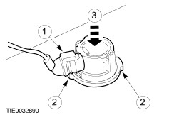
Install the parking aid sensors (left-hand side shown). - Install the sensor.
- Depress the tangs.
- Install the clamp.
| | | -
NOTE:With the aid of another technician, support the bumper cover. Connect the parking aid sensor electrical connectors. | Vehicles with parking aid built 10/2001 onwards | | -
Install the bumper cover. | | | -
NOTE:Use the templates supplied with the manufacturers instructions. NOTE:Templates shown for reference. Cut out the parking aid sensor position templates. - Left-hand side outer template.
- Left-hand side inner template.
- Right-hand side inner template.
- Right-hand side outer template.
| | | -
NOTE:Bumper cover shown removed for clarity. NOTE:Note the position of the upper edge of the templates. NOTE:Positional tolerance ± 5 mm. Using suitable tape, secure the parking aid sensor templates to the bumper cover as shown. - Left-hand side outer template.
- Left-hand side inner template.
- Right-hand side inner template.
- Right-hand side outer template.
| | | -
Using a suitable center punch and hammer, mark the position of the parking aid sensor location holes. | | | -
NOTE:Bumper cover shown removed for clarity. NOTE:Holes drilled at 4 degrees downwards into the bumper cover. - Left-hand side outer hole.
- Left-hand side inner hole.
- Right-hand side inner hole.
- Right-hand side outer hole.
| | | -
Using a suitable round file, cut the parking aid sensor cover location grooves in the bumper cover as shown (+0.5 mm, –0.0 mm). | | | -
CAUTION:The bumper cover ends must be pulled away from the fenders to prevent damage to the paintwork. Remove the bumper cover. | | | -
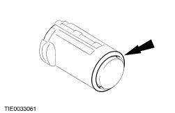
NOTE:Note the difference between the inner and outer parking aid sensor covers. NOTE:Make sure the parking aid sensor covers are installed flush with the bumper cover. Install the parking aid sensor covers (left-hand side shown). | | | -
Install the parking aid sensor rings. | | | -
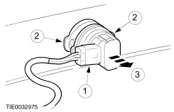
Install the parking aid sensors. - Install the housing.
- Depress the tangs.
- Install the clamp.
- Install the sensor.
| | | -
NOTE:With the aid of another technician, support the bumper cover. Connect the parking aid sensor electrical connectors. | All vehicles | | -
Install the bumper cover. - Connect the fog lamp and reversing lamp electrical connectors (if equipped).
| | | -
Install the lower pushpin retainers. | | | -
Attach the bumper cover to the fender on both sides. - Install the clip.
- Install the retaining nut.
| | | -
Attach the bumper cover to the fender splash shield on both sides. | | | -
Install the upper pushpin retainers. | |