| Removal and Installation Special Tool(s) | | Alignment Pins, Subframe 205-316 (15-097A) | | | Separator, Ball Joint 211-020 (13-006) | General Equipment Transmission jack Securing strap Materials Name Specification Grease SA-M1C9107-A CAUTION:Make sure the strut and spring assembly does not move in a forwards or rearwards direction, to prevent damage to the top mount center cup. | | -
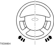
NOTE:Make sure the road wheels are in the straight ahead position. Centralize the steering and lock it in position. | | | -
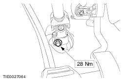
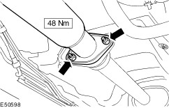
Detach the steering column shaft from the steering gear pinion. - Discard the retaining bolt.
| | | -
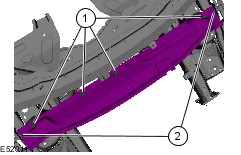
Remove the cowl panel grille.
For additional information, refer to: Cowl Panel Grille (501-02 Front End Body Panels, Removal and Installation).
| | | -
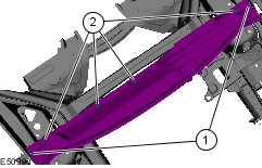
Remove the bulkhead extension panel. - Remove the retaining screws and washers.
- Detach the panel from the retaining clips.
| | | -
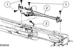
Remove the windshield wiper motor and linkage assembly. - Remove the retaining bolts.
- Detach the windshield wiper motor and linkage assembly from the vehicle body.
- Disconnect the wiper motor electrical connector.
| | | -
Disconnect the right-hand heated oxygen sensor (HO2S) and catalytic monitor sensor electrical connectors. | | | -
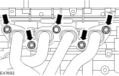
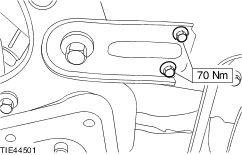
Disconnect the left-hand heated oxygen sensor (HO2S) and catalytic monitor sensor electrical connectors. | 8. Remove the components in the order indicated in the following illustration(s) and table(s). 1 - Catalytic converter heat shield retaining bolts 2 - Catalytic converter heat shield 3 - Heated oxygen sensors (HO2S) 4 - Exhaust manifold retaining nuts and bolt 9 - Engine support insulator center retaining bolt 9. Install the components in the order indicated in the following illustration(s) and table(s). 7 - Engine support insulator center retaining bolt 13 - Heated oxygen sensors (HO2S) 15 - Catalytic converter heat shield retaining bolts | | -
Connect the left-hand HO2S and catalytic monitor sensor electrical connectors. | | | -
Connect the right-hand HO2S and catalytic monitor sensor electrical connectors. | | | -
Install the windshield wiper motor and linkage assembly. - Connect the wiper motor electrical connector.
- Attach the windshield wiper motor and linkage assembly to the vehicle body.
- Install the retaining bolts.
| | | -
Install the bulkhead extension panel. - Attach the panel to the retaining clips.
- Install the retaining screws and washers.
| | | -
Install the cowl panel grille.
For additional information, refer to: Cowl Panel Grille (501-02 Front End Body Panels, Removal and Installation).
| | | -
WARNING:Install a new steering column to steering gear pinion bolt. Failure to follow this instruction may result in personal injury. NOTE:Make sure the road wheels are in the straight ahead position. Attach the steering column shaft to the steering gear pinion. - Install a new retaining bolt.
| Removal Details Item 5 : Catalytic converter to muffler and tailpipe assembly retaining nuts | | -
Raise and support the vehicle.
For additional information, refer to: Jacking (100-02 Jacking and Lifting, Description and Operation) /
Lifting (100-02 Jacking and Lifting, Description and Operation).
| | | -
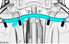
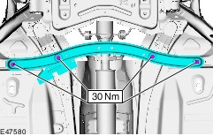
Remove the floor panel brace. | | | -
CAUTION:Over bending of the exhaust flexible pipes may cause damage resulting in failure. Support the exhaust flexible pipes with a suitable support wrap or suitable splint. | | | -
CAUTION:Support the muffler and tailpipe assembly with suitable cable ties. Loosen the exhaust flexible pipe to muffler and tailpipe assembly retaining bolts. | Item 6 : Exhaust hanger insulators CAUTION:Take care when removing the exhaust hanger insulators to prevent damage. Item 7 : Tie-rod end | | -
Remove both front wheels and tires.
For additional information, refer to: Wheel and Tire (204-04 Wheels and Tires, Removal and Installation).
| | | -
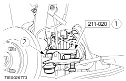
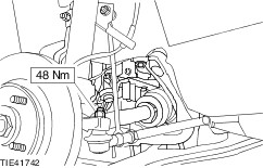
CAUTION:Leave the tie-rod end retaining nut in place to protect the ball joint stud. NOTE:Use a 5 mm Allen key to prevent the ball joint stud from rotating. Loosen the tie-rod end nut on both sides. | | | -
CAUTION:Protect the ball joint seal using a soft cloth to prevent damage. Using the special tool, detach the tie-rod end from the wheel knuckle on both sides. - Release the tie-rod end.
- Remove and discard the tie-rod end retaining nut.
| Item 8 : Stabilizer bar link | | -
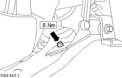
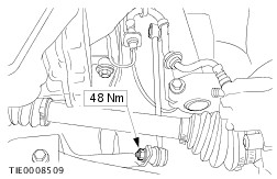
NOTE:Use a 5 mm Allen key to prevent the ball joint stud from rotating. Detach the stabilizer bar link from the stabilizer bar on both sides. | Item 10 : Front axle crossmember | | -
Detach the headlamp leveling front sensor bracket from the right-hand lower arm and secure it to one side (if equipped). | | | -
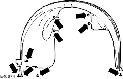
Remove the right-hand front fender splash shield. | | | -
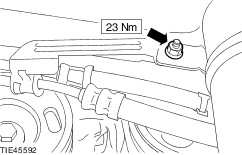
Detach the power steering fluid lines front bracket from the vehicle body. | | | -
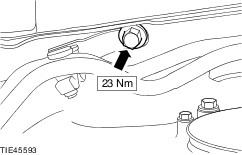
Detach the power steering fluid lines center bracket from the vehicle body. | | | -
Using a transmission jack and a wooden block, support the front axle crossmember, stabilizer bar and lower arm assembly. | | | -
WARNING:Make sure the front axle crossmember is secured to the transmission jack. Failure to follow this instruction may result in personal injury. | | | -
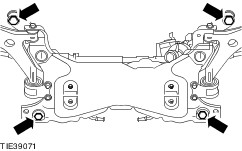
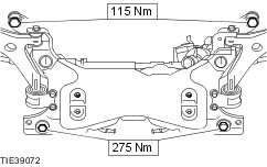
Remove the front axle crossmember bracket retaining bolts on both sides. | | | -
Remove the front axle crossmember retaining bolts (transmission jack removed for clarity). | | | -
CAUTION:To prevent damage to the power steering lines, only lower the front axle crossmember sufficiently to allow the catalytic converter to be removed. Lower the front axle crossmember. | Item 11 : Catalytic converter | | -
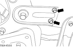
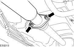
Remove the catalytic converter to catalytic converter support bracket retaining bolts. | | | -
With the aid of another technician, remove the catalytic converter. - Remove the exhaust flexible pipe to tailpipe and muffler assembly retaining bolts
| | | -
Remove the catalytic converter monitor sensors. | Installation Details Item 1 : Catalytic converter | | -
Install the catalytic converter monitor sensors. | Item 2 : Exhaust manifold retaining nuts and bolt | | -
CAUTION:Never use jointing compound forward of the catalytic converter. NOTE:Coat the catalytic converter studs with anti-seize grease. NOTE:Install a new gasket, nuts and bolt. NOTE:Do not fully tighten the exhaust manifold retaining nuts and bolt at this stage. Install the exhaust manifold retaining nuts and bolt. | Item 3 : Catalytic converter support bracket retaining bolts | | -
NOTE:Do not fully tighten the catalytic converter support bracket retaining bolts at this stage. Install the catalytic converter support bracket retaining bolts. | Item 4 : Exhaust hanger insulators | | -
CAUTION:Take care when installing the exhaust hanger insulators to prevent damage. Check the exhaust hanger insulators for damage. Install new exhaust hanger insulators as required. | Item 5 : Catalytic converter to muffler and tailpipe assembly retaining nuts | | -
NOTE:Coat the catalytic converter studs with anti-seize grease. NOTE:Install a new gasket and nuts. NOTE:Do not fully tighten the exhaust flexible pipe to muffler and tailpipe assembly retaining bolts at this stage. Install the exhaust flexible pipe to muffler and tailpipe assembly retaining bolts. | Item 6 : Front axle crossmember | | -
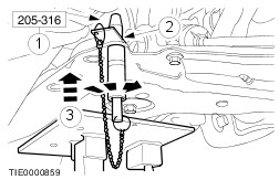
WARNING:Make sure the front axle crossmember is secured to the transmission jack. Failure to follow this instruction may result in personal injury. Using a transmission jack and the special tool, position and align the front axle crossmember. - Insert the alignment pins through the front axle crossmember alignment holes.
- Slide the locking plates into the groove of the special tool and tighten the alignment pin sleeve.
- Raise the front axle crossmember engaging the alignment pins into the chassis aligning holes.
| | | -
CAUTION:Make sure the front axle crossmember does not move while tightening the front axle crossmember retaining bolts. Install the front axle crossmember retaining bolts (transmission jack shown removed for clarity). | | | -
Install the front axle crossmember bracket retaining bolts on both sides. | | | -
Attach the power steering fluid lines center bracket to the vehicle body. | | | -
Attach the power steering fluid lines front bracket to the vehicle body. | | | -
Install the right-hand front fender splash shield. | | | -
Attach the headlamp leveling front sensor bracket to the right-hand lower arm (if equipped). | Item 8 : Tie-rod end | | -
NOTE:Install new tie-rod end retaining nuts. NOTE:Use a 5 mm Allen key to prevent the ball joint stud from rotating. Attach the tie-rod end to the wheel knuckle on both sides. | Item 9 : Stabilizer bar link | | -
NOTE:Use a 5 mm Allen key to prevent the ball joint stud from rotating. Attach the stabilizer bar link to the stabilizer bar on both sides. | Item 10 : Exhaust manifold retaining nuts and bolt | | -
Lower the vehicle to gain access to the exhaust manifold retaining nuts and bolt. | | | -
Tighten the exhaust manifold retaining nuts and bolt. | | | -
Raise and support the vehicle.
For additional information, refer to: Jacking (100-02 Jacking and Lifting, Description and Operation) /
Lifting (100-02 Jacking and Lifting, Description and Operation).
| Item 11 : Catalytic converter support bracket retaining bolts | | -
Tighten the catalytic converter to catalytic converter support bracket retaining bolts. | Item 12 : Catalytic converter to muffler and tailpipe assembly retaining nuts | | -
Tighten the catalytic converter to muffler and tailpipe assembly retaining nuts. | | | -
Install the floor panel brace. | Item 14 : Catalytic converter heat shield | | -
Feed the H2OS wiring harness through the heat shield. | |