
Fusion FWD L4-2.3L VIN Z (2007)
C3-C4
Normal Operation
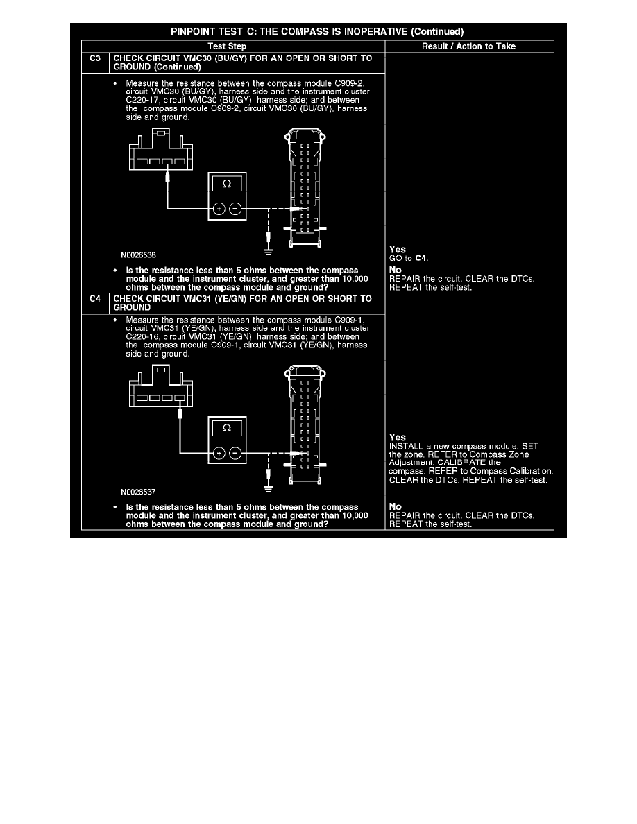
The compass module receives voltage from the smart junction box (SJB) through circuit CBP19 (BN/WH) and is grounded through circuit GD139
(BK/YE). The compass module communicates the vehicle direction to the instrument cluster through circuits VMC30 (BU/GY) and VMC31 (YE/GN)
and the direction is displayed in the instrument cluster.
DTC U2013 - is a continuous DTC that sets if the instrument cluster does not receive compass data on circuits VMC30 (BU/GY) and VMC31
(YE/GN).
Possible Causes
-
Fuse
-
Circuit CBP19 (BN/WH) open
-
Circuit GD139 (BK/YE) open
-
Circuit VMC30 (BU/GY) open or short to ground
-
Circuit VMC31 (YE/GN) open or short to ground
-
Compass module
Test D: The Compass Is Inaccurate
PINPOINT TEST D: THE COMPASS IS INACCURATE