
Fusion FWD L4-2.3L VIN Z (2007)
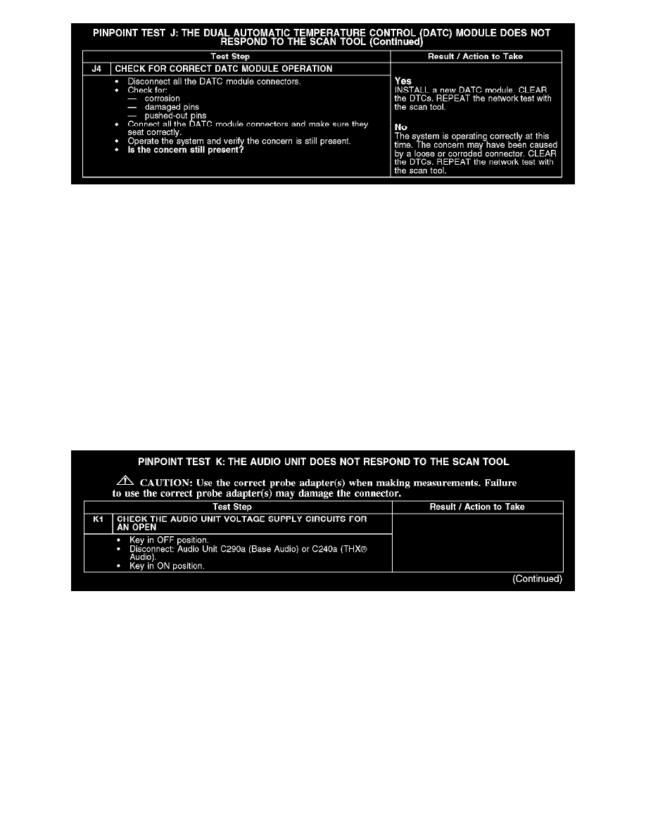
J4
Normal Operation
The DATC module communicates with the scan tool through the medium speed controller area network (MS-CAN). Circuits VDB06 (GY/OG)
(MS-CAN +) and VDB07 (VT/OG) (MS-CAN -) provide the network connection to the DATC module. The DATC module is only on vehicles
equipped with automatic climate control. The DATC module shares the MS-CAN network with the smart junction box (SJB), the instrument cluster,
the audio unit, the THX(R) amplifier (if equipped), the satellite radio receiver (if equipped), the driver seat module (DSM) (if equipped), the driver
door module (DDM) (if equipped) and the climate controlled seat module (if equipped). Voltage for the DATC module is provided by circuits CBP20
(YE/VT) and SBP07 (WH/RD). Circuit GD116 (BK/VT) provides ground.
Possible Causes
-
Fuse
-
Circuit CBP20 (YE/VT) open
-
Circuit GD116 (BK/VT) open
-
Circuit SBP07 (WH/RD) open
-
Circuit VDB06 (GY/OG) open (MS-CAN +)
-
Circuit VDB07 (VT/OG) open (MS-CAN -)
-
DATC module
Test K: The Audio Unit Does Not Respond To The Scan Tool
PINPOINT TEST K: THE AUDIO UNIT DOES NOT RESPOND TO THE SCAN TOOL
K1