
Fusion FWD L4-2.3L VIN Z (2007)
All wheel drive (AWD) vehicles
5. Remove and discard the upper arm outboard bolt and nut.
-
To install, tighten the nut to 110 Nm (81 ft. lbs.) with the suspension at the bushing fastener tightening position.
All vehicles
6. Carefully lower the trailing arm and remove the jack.
7. NOTE: Position the shock absorber as necessary to remove the upper arm.
NOTE: When tightening the upper arm inboard bolt the suspension must be at the bushing fastener tightening position.
Remove and discard the upper arm inboard bolt and remove the upper arm.
-
To install, tighten the bolt to 100 Nm (74 ft. lbs.) and then rotate an additional 90 degrees.
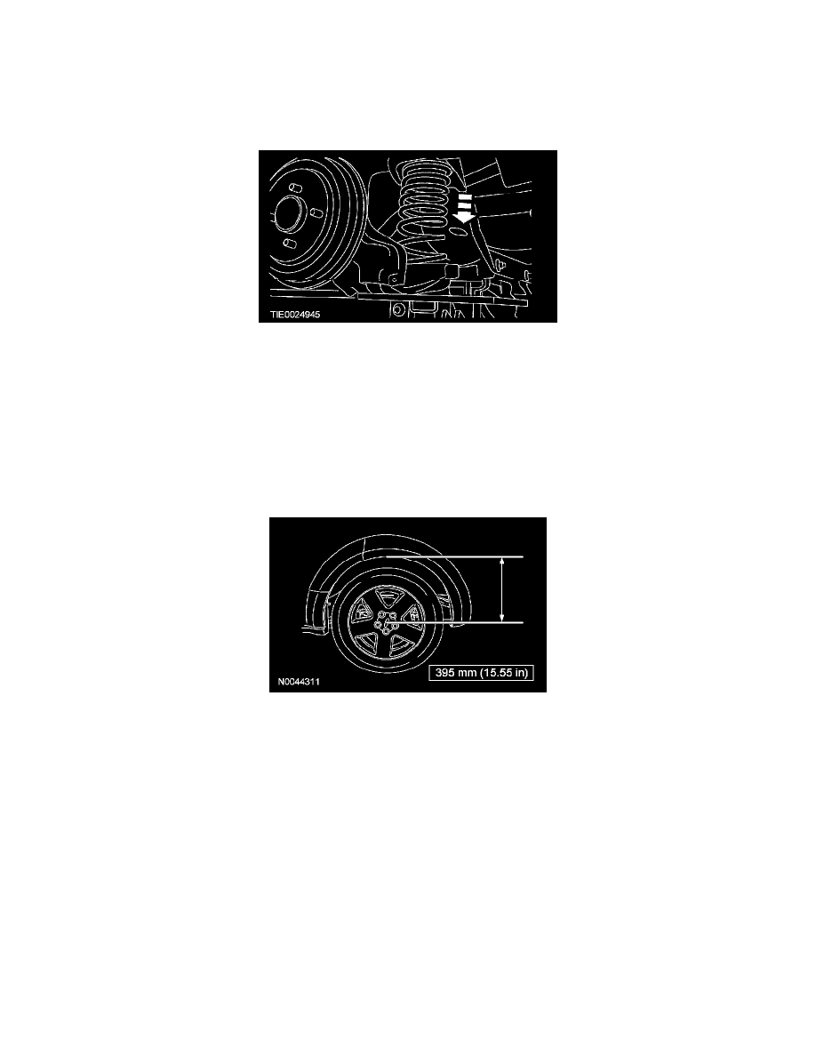
8. CAUTION: Before tightening any suspension bushing fasteners, the suspension must be at the bushing fastener tightening position. Use a suitable
jack to raise the suspension until the distance between the center of the hub and the lip of the fender is equal to 395 mm (15.55 inch).
To install, reverse the removal procedure.
9. Check and, if necessary, adjust the rear camber.
Lower Arm
Lower Arm
NOTE: Front wheel drive (FWD) shown, all wheel drive (AWD) similar.