
Fusion FWD L4-2.5L Hybrid (2010)
-------------------------------------------------
C3 CHECK THE HS-CAN TERMINATION RESISTANCE
-
Disconnect the scan tool cable from the Data Link Connector (DLC).
-
Measure the resistance between the DLC C251-6, circuit VDB04 (WH/BU), harness side and the DLC C251-14, circuit VDB05 (WH), harness
side.
-
Is the resistance between 54 and 66 ohms?
Yes
GO to C6.
No
GO to C4.
-------------------------------------------------
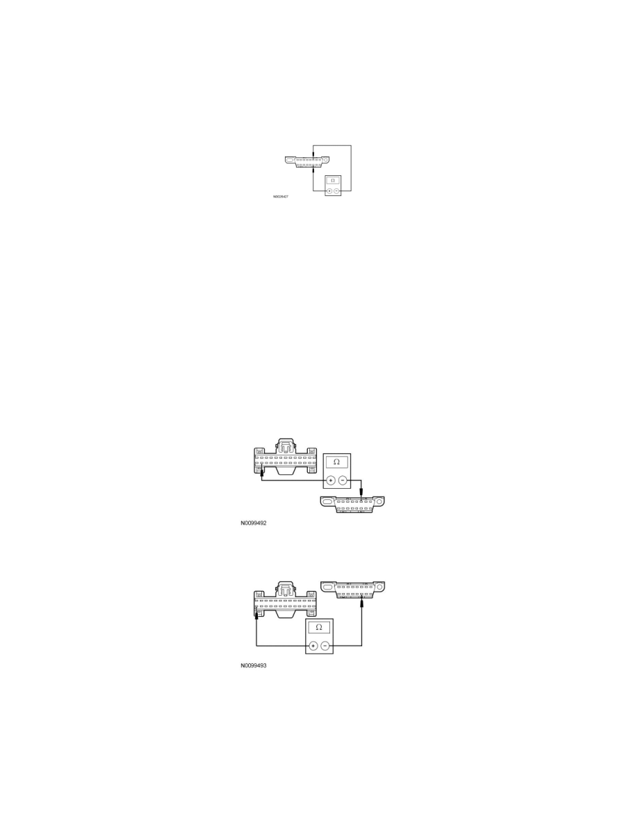
C4 CHECK THE HS-CAN CIRCUITS BETWEEN THE DLC AND THE IPC FOR AN OPEN - GASOLINE
-
Measure the resistance between the IPC C220-25, circuit VDB04 (WH/BU), harness side and the DLC C251-6, circuit VDB04 (WH/BU), harness
side.
-
Measure the resistance between the IPC C220-26, circuit VDB05 (WH), harness side and the DLC C251-14, circuit VDB05 (WH), harness side.
-
Are the resistances less than 5 ohms?
Yes
GO to C6.
No
REPAIR the circuit in question. CONNECT the negative battery cable. CLEAR the DTCs. REPEAT the network test with the scan tool.