
Hybrid Powertrain Management Control Systems
Pinpoint Test R: The Side Obstacle Detection Control Module - Left (SOD-L) Does Not Respond To The Scan Tool
Refer to Wiring Diagram Set 14 (Fusion/Milan/MKZ, Fusion Hybrid/Milan Hybrid), Module Communications Network for schematic and connector
information. See: Diagrams/Electrical Diagrams/Diagrams By Number
Refer to Wiring Diagram Set 131 (Fusion/Milan/MKZ, Fusion Hybrid/Milan Hybrid), Parking Aid for schematic and connector information. See:
Diagrams/Electrical Diagrams/Diagrams By Number
Normal Operation
The Side Obstacle Detection Control Module - Left (SOD-L) communicates with the scan tool through the Medium Speed Controller Area Network
(MS-CAN).
This pinpoint test is intended to diagnose the following:
-
Fuse
-
Wiring, terminals or connectors
-
SOD-L
PINPOINT TEST R: THE SOD-L DOES NOT RESPOND TO THE SCAN TOOL
NOTICE: Use the correct probe adapter(s) when making measurements. Failure to use the correct probe adapter(s) may damage the
connector.
NOTE: Failure to disconnect the battery when instructed will result in false resistance readings. Refer to Battery.
-------------------------------------------------
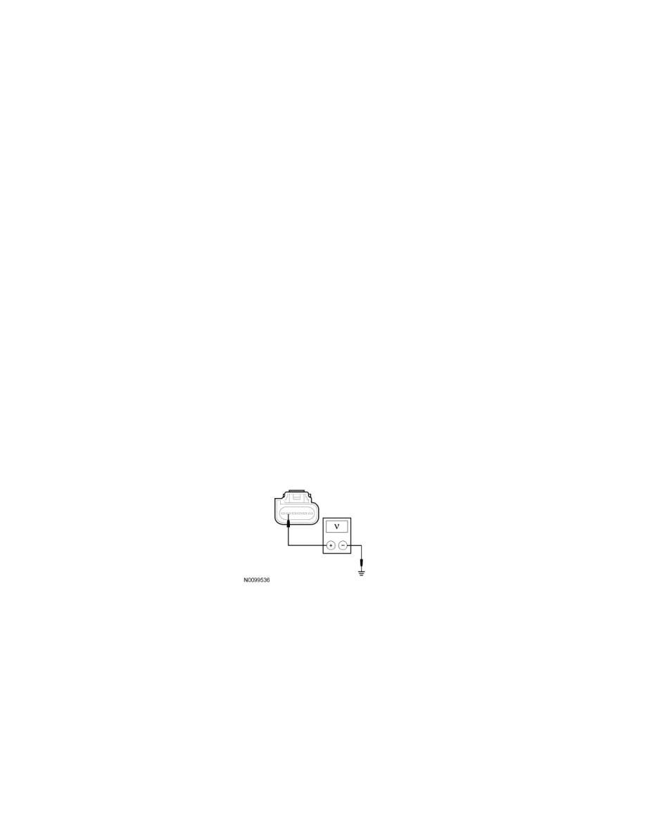
R1 CHECK THE SOD-L VOLTAGE SUPPLY CIRCUIT FOR AN OPEN
-
Ignition OFF.
-
Disconnect: SOD-L C4230 .
-
Ignition ON.
-
Measure the voltage between the SOD-L C4230-5, circuit CBP35 (YE/GY), harness side and ground.
-
Is the voltage greater than 10 volts?
Yes
GO to R2.
No
VERIFY the Smart Junction Box (SJB) fuse 35 (10A) is OK. If OK, REPAIR the circuit in question. If not OK, REFER to the Wiring Diagrams to
identify the possible causes of the circuit short See: Diagrams/Electrical Diagrams/Diagrams By Number. CLEAR the DTCs. REPEAT the network test
with the scan tool.
-------------------------------------------------
R2 CHECK THE SOD-L GROUND CIRCUIT FOR AN OPEN