
Fusion FWD L4-2.5L Hybrid (2010)
Yes
GO to Z3.
No
REPAIR the circuit in question. CONNECT the negative battery cable. CLEAR the DTCs. REPEAT the network test with the scan tool.
-------------------------------------------------
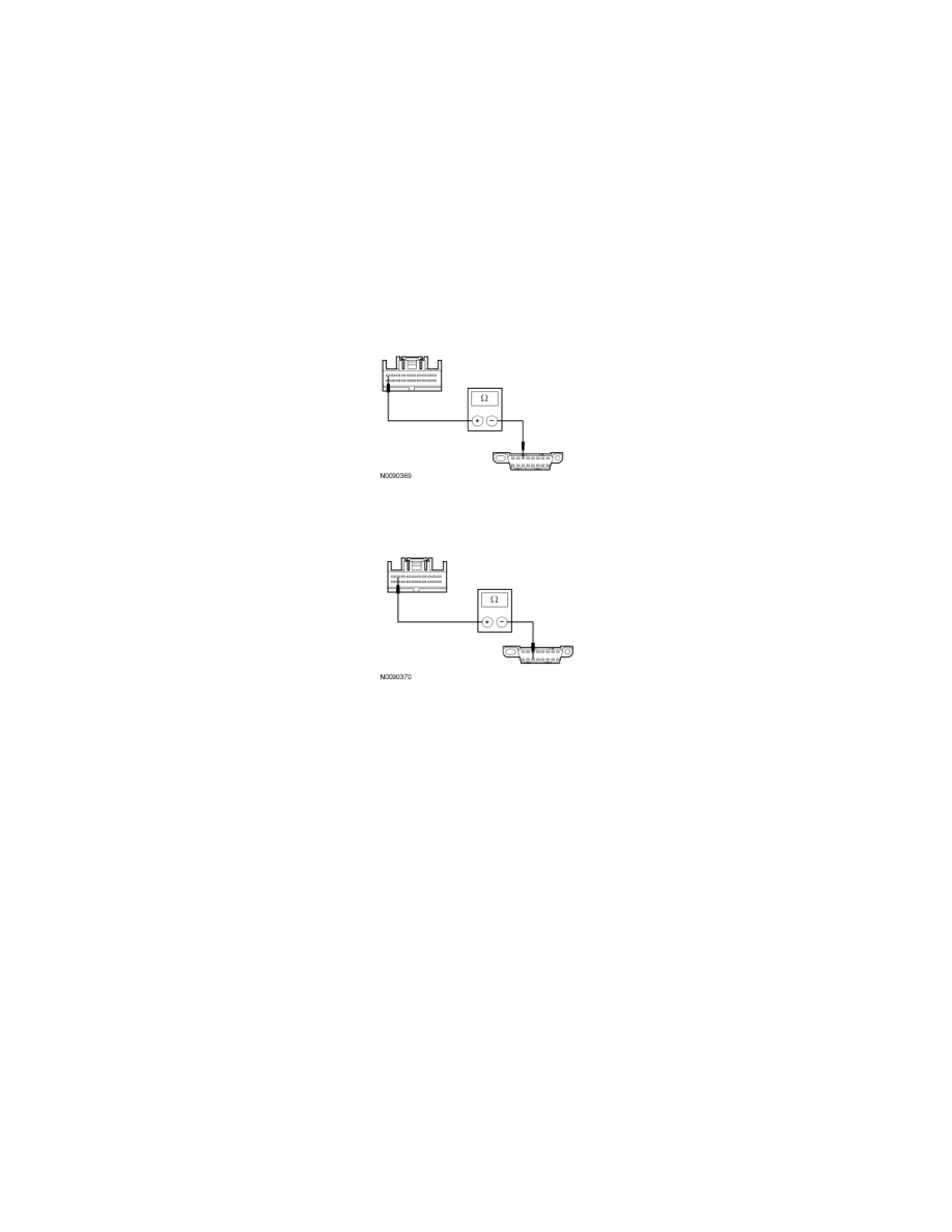
Z3 CHECK THE MS-CAN CIRCUITS BETWEEN THE DSM AND THE DLC FOR AN OPEN
-
Disconnect: DSM C3299d .
-
Measure the resistance between the DSM C3299d-10, circuit VDB06 (GY/OG), harness side and the DLC C251-3, circuit VDB06 (GY/OG),
harness side.
-
Measure the resistance between the DSM C3299d-9, circuit VDB07 (VT/OG), harness side and the DLC C251-11, circuit VDB07 (VT/OG),
harness side.
-
Are the resistances less than 5 ohms?
Yes
CONNECT the negative battery cable. GO to Z4.
No
REPAIR the circuit in question. CONNECT the negative battery cable. CLEAR the DTCs. REPEAT the network test with the scan tool.
-------------------------------------------------
Z4 CHECK FOR CORRECT DSM OPERATION
-
Disconnect all the DSM connectors.
-
Check for:
-
corrosion
-
damaged pins
-
pushed-out pins
-
Connect all the DSM connectors and make sure they seat correctly.
-
Operate the system and verify the concern is still present.
-
Is the concern still present?
Yes
INSTALL a new DSM. REFER to Body Control Systems. REPEAT the network test with the scan tool.