
Fusion FWD L4-2.5L Hybrid (2010)
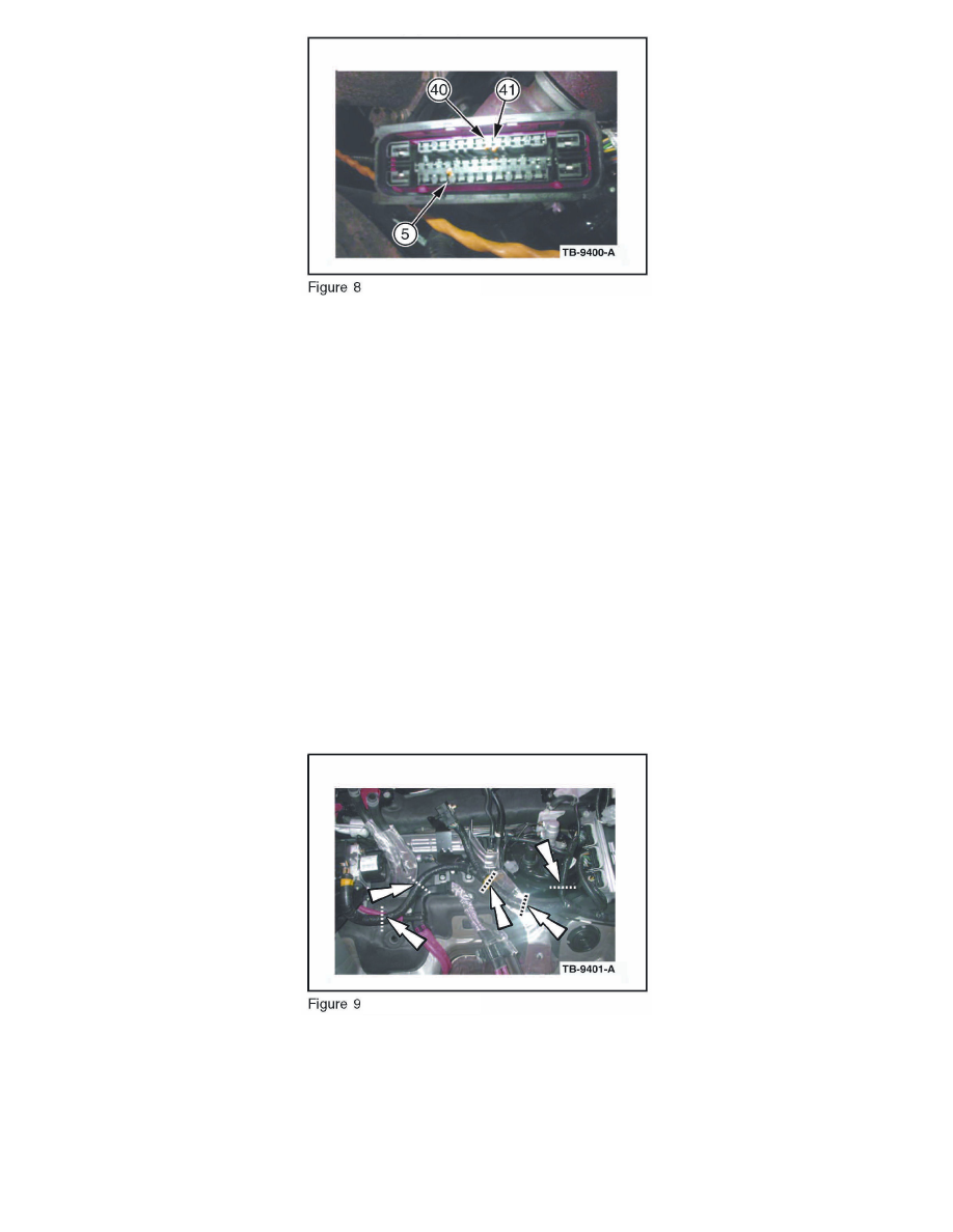
16. Identify and mark the wires and terminals to be removed. (Figure 8)
a. Cavity 5 - Green wire
b. Cavity 40 - Blue/Brown wire
C. Cavity 41 - Yellow/Blue wire
17. Re-pin the ABS connector using Rotunda terminal removal kit 418-D631 or equivalent.
a. Remove green wire and terminal from cavity 5. Insert Green wire and terminal of the Cutoff Pressure Sensor Jumper into cavity 5.
b. Remove Blue/Brown wire and terminal from cavity 40. Insert Blue/Brown wire and terminal of the Cutoff Pressure Sensor Jumper into cavity 40.
c. Remove Yellow/Blue wire and terminal from cavity 41. Insert Yellow/Blue wire and terminal of the Cutoff Pressure Sensor Jumper into cavity
41.
18. Install the red terminal lock into the ABS connector.
19. Install a new tie strap retaining the wire bundle to the ABS connector.
20. Cut the terminal ends from the removed circuits and tape to the adjacent wire harness.
21. Connect the ABS connector, then secure the wire harness pushpin retainer to the support bracket.
22. Tie strap the Cutoff Pressure Sensor Jumper along the ABS harness bundle with (5) tie straps spaced 7 7/8" to 11.13/16" (20-30 cm) apart, and cut
off excess length. (Figure 9)
23. Install the underbody cover.
24. Install the upper and lower cowl panels following (WSM), Section 501-02.
25. Install the high voltage junction box into the retainer.