
Fusion FWD L4-2.5L Hybrid (2010)
Throttle Position Sensor: Description and Operation
ENGINE CONTROL COMPONENTS
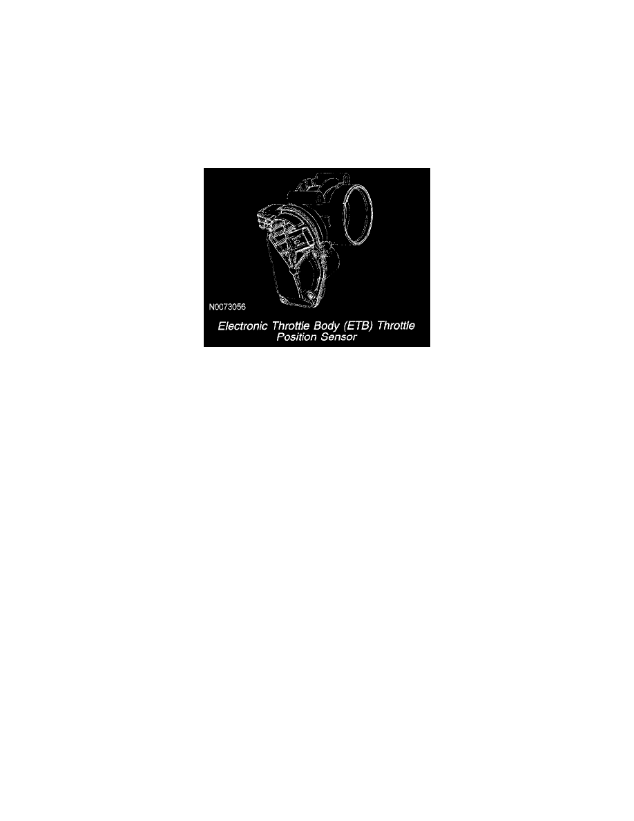
Electronic Throttle Body (ETB) Throttle Position Sensor
The ETB throttle position sensor has two signal circuits in the sensor for redundancy. The redundant ETB throttle position signals are required for
increased monitoring. The first ETB throttle position sensor signal (TP1) has a negative slope (increasing angle, decreasing voltage) and the second
signal (TP2) has a positive slope (increasing angle, increasing voltage). The two ETB throttle position sensor signals make sure the PCM receives a
correct input even if one signal has a concern. There is one reference voltage circuit and one signal return circuit for the sensor. The reference voltage
circuit and the signal return circuit is shared with the reference voltage circuits and signal return circuits used by the APP sensor. For additional
information, refer to the description of the Torque-Based Electronic Throttle Control (ETC). See: Computers and Control Systems/Electronic Throttle
Control Module/Description and Operation
Electronic Throttle Body (ETB) Throttle Position Sensor