
Fusion FWD V6-3.0L (2009)
The ABS module communicates with the scan tool through the High Speed Controller Area Network (HS-CAN). Circuits VDB04 (WH/BU) (HS-CAN
+) and VDB05 (WH) (HS-CAN -) provide the network connection to the ABS module. Voltage for the ABS module is provided by circuit CBP19
(BN/WH). Ground is provided by circuit GD123 (BK/GY).
This pinpoint test is intended to diagnose the following:
-
Fuse
-
Wiring, terminals or connectors
-
ABS module
PINPOINT TEST C: THE ABS MODULE DOES NOT RESPOND TO THE SCAN TOOL
NOTICE: Use the correct probe adapter(s) when making measurements. Failure to use the correct probe adapter(s) may damage the
connector.
NOTE: Failure to disconnect the battery when instructed will result in false resistance readings. Refer to Battery.
-------------------------------------------------
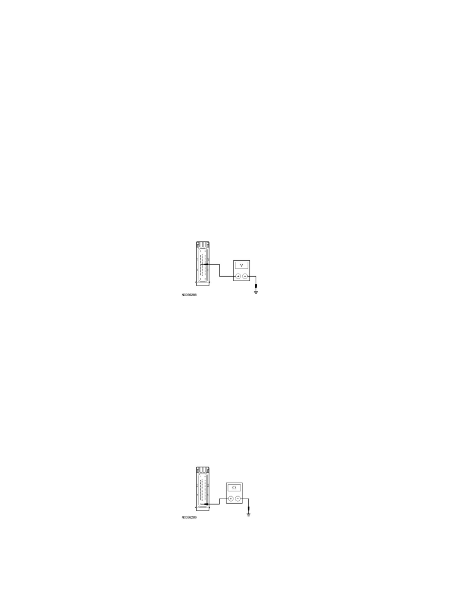
C1 CHECK THE ABS MODULE VOLTAGE SUPPLY CIRCUIT FOR AN OPEN
-
Ignition OFF.
-
Disconnect: ABS Module C135.
-
Ignition ON.
-
Measure the voltage between the ABS module C135-8, circuit CBP19 (BN/WH), harness side and ground.
-
Is the voltage greater than 10 volts?
Yes
GO to C2.
No
VERIFY the Smart Junction Box (SJB) fuse 28 (10A) is OK. If OK, REPAIR the circuit. CLEAR the DTCs. REPEAT the network test with the scan
tool.
-------------------------------------------------
C2 CHECK THE ABS MODULE GROUND CIRCUIT FOR AN OPEN
-
Ignition OFF.
-
Disconnect: Negative Battery Cable.
-
Measure the resistance between the ABS module C135-16, circuit GD123 (BK/GY), harness side and ground.
-
Is the resistance less than 5 ohms?
Yes
CONNECT the negative battery cable. GO to C3.