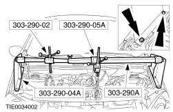
| Removal Special Tool(s) | | Support Bar, Engine 303-290A (21-140A) | | | Adapter for 303-290A 303-290-02 (21-140-02) | | | Adapter for 303-290A 303-290-04A (21-140-04A) | | | Adapter for 303-290A 303-290-05A (21-140-05A) | | | Socket, Flywheel Bolt 303-502 (21-205) | General Equipment Retaining straps Transmission jack Removal All vehicles | | -
Disconnect the positive cable from the battery terminal clamp. | | | -
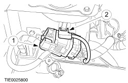
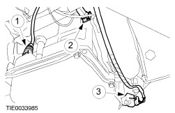
Disconnect the electrical connectors. - Disconnect the engine wiring harness electrical connector.
- Disconnect the engine coolant level sensor electrical connector.
| | | -
Remove the battery side cover. - Detach the cooling system degas hose from the battery side cover.
- Detach the engine wiring harness electrical connector from the bracket.
| | | -
Remove the battery tray. - Detach the engine wiring harness rail from the battery tray.
- Detach the coolant hose from the battery tray.
| | | -
Disconnect the battery positive cable and the ignition switch to starter motor cable from the starter motor. | | | -
Detach the selector lever cable from the transaxle shift lever. - Detach the selector lever cable from the transaxle shift lever.
- Detach the selector cable from the retaining bracket.
| | | -
Detach the selector lever cable from the retaining clip. | | | -
Disconnect the turbine shaft speed (TSS) sensor electrical connector. | | | -
Detach the transmission fluid cooler from the transaxle case. - Remove and discard the O-ring seal.
| | | -
Detach the coolant pipe from the transaxle. | | | -
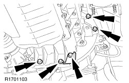
Remove the transaxle upper retaining studs. | | | -
Disconnect the transaxle wiring harness electrical connectors. - Disconnect the solenoid valve control unit electrical connector.
- Disconnect the output shaft speed (OSS) sensor electrical connector.
- Disconnect the transmission range (TR) sensor electrical connector.
| | | -
Install the special tools. | | | -
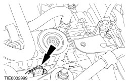
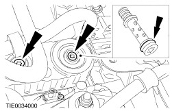
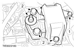
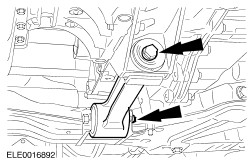
Remove the engine rear mount. - Remove the bolt.
- Remove and discard the bolts and the nut.
| | | -
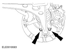
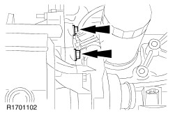
Detach the lower arms from the wheel knuckles. | | | -
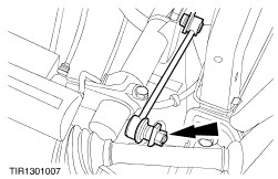
Detach the stabilizer bar links from the stabilizer bar on both sides. | Vehicles with high intensity discharge headlamps | | -
Disconnect the headlamp levelling sensor electrical connector. | All vehicles | | -
Detach the power steering gear from the front axle crossmember and secure it. | | | -
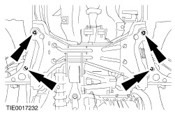
Remove the front axle crossmember. | | | -
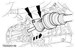
CAUTION:Secure the halfshaft to prevent damage to the constant velocity (CV) joints. The inner CV joint must not be bent more than 20 degrees. The outer CV joint must not be bent more than 50 degrees. CAUTION:Make sure that the halfshaft seal is not damaged. CAUTION:Cap the transaxle to prevent oil loss or dirt ingress. Detach the right-hand halfshaft and the intermediate shaft from the transaxle and secure them to one side. - Allow the fluid to drain into a suitable container.
| | | -
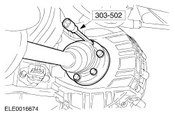
CAUTION:Secure the halfshaft to prevent damage to the constant velocity (CV) joints. The inner CV joint must not be bent more than 20 degrees. The outer CV joint must not be bent more than 50 degrees. Using the special tool, detach the left-hand halfshaft from the transaxle and secure it to one side. | | | -
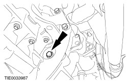
Remove the engine support insulator. | | | -
Disconnect the vehicle speed sensor (VSS) electrical connector. | | | -
Using the special tools, lower the engine and transaxle assembly. | | | -
Remove the torque converter retaining nuts (three nuts). | | | -
WARNING:Make sure that the torque converter remains in the torque converter housing. Failure to follow this instruction may result in personal injury. | | | -
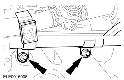
Remove the transaxle right-hand retaining nuts. | | | -
Remove the transaxle left-hand retaining bolts. | |