| Removal and Installation Special Tool(s) | | Pinion Bearing Cone Remover 205-D002 (D79L-4621-A) | | | Impact Slide Hammer 100-001(T50T-100-A) | | | Front Hub Remover 205-D070 (D93P-1175-B) or equivalent | | | Pinion Bearing Cup Replacer 205-014 (T60K-4614-A) | | | Differential Bearing Cup Replacer 308-153 (T88C-7025-BH) | | | Handle 205-153 (T80T-4000W) | | | Wheel Bearing Adapter 205-D015 (D80L-630-4) | | | Differential Bearing Cup Replacer 308-153 | | | Pinion Bearing Cup Replacer 205-014 (T60K-4616-A) | Removal All vehicles | | -
Remove the brake shoes. For additional information refer to Section 206-02 Drum Brake. | | | -
Remove the rear halfshaft nut. | | | -
Using the the special tool, loosen the halfshaft from the wheel hub. | | | -
Using the special tools, remove the wheel hub. | | | -
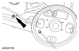
NOTE:This step may not be necessary if the inner wheel bearing race remains in the wheel knuckle, after removing the wheel hub. Using the special tool, press the inner wheel bearing race from the wheel hub. | Vehicles with ABS | | -
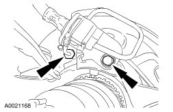
Position the anti-lock brake (ABS) sensor aside. - Remove the ABS sensor bolt and bracket bolts.
- Position the ABS sensor aside.
| All vehicles | | -
Disconnect the parking brake cable. - Remove the parking brake cable bolt from the wheel knuckle.
| | | -
Disconnect the brake line from the wheel cylinder. - Remove the brake line bracket bolt.
| | | -
Support the wheel knuckle. | | | -
Remove the lower shock absorber nut. | | | -
NOTE:It may be necessary to hold the ball joint stud to keep it from turning while removing the nut. Disconnect the lower ball joint. | | | -
NOTE:It may be necessary to hold the ball joint stud to keep it from turning while removing the nut. Disconnect the upper ball joint. | | | -
NOTE:Note the position of the spring insulator and spring for installation. Remove the spring. - Lower the support to the wheel knuckle.
| | | -
Remove the wheel knuckle cam bolt. - Mark the position of the adjustment cam notch.
- Remove the wheel knuckle cam bolt.
| | | -
Remove the wheel knuckle. - Remove the wheel knuckle cam.
- Remove the wheel knuckle.
| | | -
Using the special tools, press the outer wheel bearing race from the wheel knuckle. | Installation All vehicles | | -
Using the special tools, install a new wheel bearing into the wheel knuckle. | | | -
Install the snap ring into the wheel knuckle. | | | -
Using the special tools, install the wheel hub. | | | -
Position the wheel knuckle and install the wheel knuckle cam. - Position the halfshaft into the wheel hub.
| | | -
Install the wheel knuckle cam bolt loosely. | | | -
Support the wheel knuckle and install the spring. | | | -
Install the lower shock absorber nut. | | | -
Install the upper ball joint. | | | -
Install the lower ball joint. | | | -
Tighten the wheel knuckle cam bolt. - Align the wheel knuckle cam.
- Tighten the wheel knuckle cam bolt.
| | | -
Install the brake line to the wheel cylinder. - Install the brake line bracket bolt.
| | | -
Install the parking brake cable onto the backing plate. - Install the bolt.
- Install the parking brake cable onto the backing plate.
| Vehicles with ABS | | -
Position the anti-lock (ABS) brake sensor and bracket bolts. | All vehicles | | -
Install the halfshaft nut. | | | -
Install the brake shoes. For additional information, refer to Section 206-02 Drum Brake. | | |