| Diagnosis and Testing Special Tool(s) | | Diagnostic Tool, Restraint System 418-F403 or equivalent | | | 73III Automotive Meter 105-R0057 or equivalent | | | Vehicle Communication Module (VCM) and Integrated Diagnostic System (IDS) software with appropriate hardware, or equivalent scan tool | | | Flex Probe Kit 105-R025C or equivalent | Principles of Operation The horn relay B+ power and the horn relay switched power are supplied through circuit 1682 (RD/LB). The horn relay is controlled by the horn switch. The horn relay is grounded through the horn switch by circuit 6 (YE/LG). When the horn switch is pressed, the horn relay control circuit 6 (YE/LG) is grounded. The relay is then closed causing B+ voltage to be applied to circuit 1 (DB), sounding the horn. The horn relay is powered on both the control and controlled sides by circuit 1682 (RD/LB). When the horn switch is pressed, the horn relay control circuit 6 (YE/LG) is grounded through the horn switch. The horn relay is then energized, allowing battery voltage to flow through the horn relay to the horn through circuit 1 (DB), enabling the horns to sound. When the vehicle security system is armed, the smart junction box (SJB) provides a momentary ground to the horn relay control side to indicate the system is armed, and a continuous ground when an intrusion is detected. For additional information on the anti-theft system, refer to Section 419-01A Anti-Theft - ActiveSection 419-01B Anti-Theft - Passive. The SJB utilizes a protective circuit strategy for many of its outputs (for example, the headlamp output circuit). Output loads (current level) are monitored for excessive current (typically short circuits) and are shut down (turns off the voltage or ground provided by the module) when a fault is detected. A continuous DTC is stored at that time for the fault. The circuit will then reset after an ignition cycle or customer demand of the function (switching the component on, 30-minute battery saver being energized). When an excessive circuit load occurs several times, the module shuts down the output until a service procedure is performed. At the same time, the continuous DTC that was stored on the first failure will not clear by a command to clear the continuous DTCs. The module will not allow this code to be cleared or the circuit restored to normal until a successful on-demand self-test proves that the fault has been repaired. After the on-demand self-test has successfully completed (no on-demand DTCs present), the continuous DTC will have been cleared and the circuit function will return. Inspection and Verification - Verify the customer concern.
- Visually inspect the following for obvious signs of mechanical or electrical damage.
Visual Inspection Chart | Mechanical | Electrical | - Clockspring
- Horn
- Horn switch
- Horn relay
| - Battery junction box (BJB) fuse 21 (40A)
- Smart junction box (SJB) fuse 20 (15A)
- Clockspring
- Circuitry
- SJB
| - If an obvious cause for an observed or reported concern is found, correct the cause (if possible) before proceeding to the next step.
-
NOTE:Make sure to use the latest scan tool software release. If the cause is not visually evident, connect the scan tool to the data link connector (DLC). -
NOTE:The vehicle communication module (VCM) LED prove-out confirms power and ground from the DLC are provided to the VCM. If the scan tool does not communicate with the VCM: - Check the VCM connection to the vehicle.
- Check the scan tool connection to the VCM.
- If the scan tool does not communicate with the vehicle:
- Verify the ignition key is in the ON position.
- Verify the scan tool operation with a known good vehicle.
- Carry out the network test:
- If the network test passes, retrieve and record the continuous memory DTCs.
- Clear the continuous DTCs and carry out the self-test diagnostics for the SJB.
- If the DTCs retrieved are related to the concern, go to the Smart Junction Box (SJB) Diagnostic Trouble Code (DTC) Index. For all other DTCs, refer to Section 419-10 Multifunction Electronic Modules.
- If no DTCs related to the concern are retrieved, GO to Symptom Chart.
Smart Junction Box (SJB) Diagnostic Trouble Code (DTC) Index | DTC | Description | Action | | B1217 | Horn Relay Coil Circuit Failure | If the horn is inoperative or if the horn is always on. | | B1218 | Horn Relay Coil Short to Battery | NOTE:Check all other systems for correct operation first. RUN the on-demand self-test (required to clear certain DTCs). If DTC B1218 is retrieved again, INSTALL a new SJB. REFER to Section 419-10 Multifunction Electronic Modules. TEST the system for normal operation. | | All other DTCs | — | REFER to Section 419-10 Multifunction Electronic Modules. | Symptom Chart Symptom Chart | Symptom | Possible Sources | Action | | The horn is inoperative | * Fuse(s) * Circuitry * Horn relay * Horn * Clockspring * Horn switch (part of the driver air bag) * Smart junction box (SJB) | * | | The horn is always on | * Circuitry * Horn relay * Clockspring * Horn switch (part of the driver air bag) * Horn switch harness * SJB | * | Pinpoint Tests Pinpoint Test A: The Horn Is Inoperative Refer to Wiring Diagrams Cell 44, for schematic and connector information. Normal Operation The horn relay B+ power is supplied through circuit 1682 (RD/LB). The horn relay is controlled by the horn switch. The horn relay is grounded through the horn switches by circuit 6 (YE/LG). When the horn switch is pressed, the horn relay control circuit 6 (YE/LG) is grounded through circuit 57 (BK). The relay is then closed causing B+ voltage to be applied to circuit 1 (DB), sounding the horns. The smart junction box (SJB) can also supply a ground for the horn relay coil. DTC B1217 — sets when the horn relay coil detects a circuit failure. Possible Causes - Fuse(s)
- Circuit 1 (DB) open
- Circuit 6 (YE/LG) open
- Circuit 57 (BK) open
- Circuit 1682 (RD/LB) open
- Horn relay
- Horn
- Clockspring
- Horn switch (part of the driver air bag)
- SJB
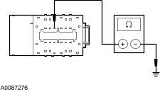
| PINPOINT TEST A : THE HORN IS INOPERATIVE | CAUTION:Use the correct probe adaptor(s) when making measurements. Failure to use the correct probe adaptor(s) may damage the connector. | | TEST CONDITIONS | DETAILS/RESULTS/ACTIONS | | A1: CHECK CIRCUIT 6 (YE/LG) FOR CONTINUITY TO GROUND | | | 1 Ignition switch in position 0. | | | 2 Disconnect SJB . | | | 3 Measure the resistance between the SJB C2280a-14, circuit 6 (YE/LG), harness side and ground while pressing and releasing the horn switch. | | | Is the resistance less than 5 ohms with the horn switch pressed and greater than 10,000 ohms with the horn switch released? Yes No | | A2: CHECK THE CLOCKSPRING AND THE SWITCHES FOR CONTINUITY | | | 1 | | | 2 Disconnect Clockspring . | | | 3 Measure the resistance between the lower clockspring connector pin 4, component side, and the lower clockspring connector pin 5, component side while pressing and releasing the horn switch. | | | Is the resistance less than 5 ohms with the horn switch pressed and greater than 10,000 ohms with the horn switch released? Yes No | | A3: CHECK THE CLOCKSPRING FOR OPENS | | | 1 | | | 2 Disconnect Horn Switch Harness. | | | 3 Measure the resistance between the upper clockspring connector pin 4, component side, and the lower clockspring connector pin 4, component side. | | | 4 Measure the resistance between the upper clockspring connector pin 5, component side, and the lower clockspring connector pin 5, component side. | | | Are the resistances less than 5 ohms? Yes No | | A4: CHECK THE STEERING WHEEL SWITCH HARNESS | | | 1 Inspect the steering wheel switch harness for chafing, opens or possible shorts. | | | Is the steering wheel switch harness OK? Yes No | | A5: CHECK CIRCUIT 57 (BK) FOR AN OPEN | | | 1 Measure the resistance between the clockspring C218a-5, circuit 57 (BK), harness side and ground. | | | Is the resistance less than 5 ohms? Yes No | | A6: CHECK THE HORNS | | | 1 Connect a fused (15A) jumper wire between the SJB C2280b-29, circuit 1682 (RD/LB), harness side and the SJB C2280b-31, circuit 1 (DB), harness side. | | | Does the horn sound? Yes REMOVE the jumper wire. VERIFY the SJB fuse 20 (15A) is OK. If OK, GO to A8. . No | | A7: CHECK CIRCUIT 1 (DB) FOR VOLTAGE | | | 1 Disconnect Suspect Horn(s). | | | 2 With the jumper wire still connected, measure the voltage between the left horn C1101-1, circuit 1 (DB), harness side and ground; circuit 1 (DB), harness side and ground. | | | Is the voltage greater than 10 volts? Yes INSTALL a new horn. REFER to Horn in this section. TEST the system for normal operation. No REPAIR the circuit. TEST the system for normal operation. | | A8: CHECK FOR CORRECT SJB OPERATION | | | 1 Disconnect all the SJB connectors. | | | 2 Check for: | | | 3 Connect all the SJB connectors and make sure they seat correctly. | | | 4 Operate the system and verify the concern is still present. | | | Is the concern still present? Yes No The system is operating correctly at this time. The concern may have been caused by a loose or corroded connector. CLEAR the DTCs. REPEAT the self-test. TEST the system for normal operation. | Pinpoint Test B: The Horn Is Always On Normal Operation The horn relay B+ power is supplied through circuit 1682 (RD/LB). The horn relay is controlled by the horn switch. The horn relay is grounded through the horn switch by circuit 6 (YE/LG). When the horn switch is pressed, the horn relay control circuit 6 (YE/LG) is grounded through circuit 57 (BK). The relay is then closed causing B+ voltage to be applied to circuit 1 (DB), or circuit 640 (RD/YE) sounding the horns. The smart junction box (SJB) can also supply a ground for the horn relay coil. DTC B1217 — sets when the horn relay coil detects a circuit failure. Possible Causes - Circuit 1 (DB) short to voltage
- Circuit 6 (YE/LG) short to ground
- Circuit 640 (RD/YE) short to voltage
- Horn relay
- Clockspring
- Horn switch (part of the driver air bag)
- Horn switch harness
- SJB
| PINPOINT TEST B : THE HORN IS ALWAYS ON | | TEST CONDITIONS | DETAILS/RESULTS/ACTIONS | | B1: CHECK THE HORN CIRCUITS FOR A SHORT TO VOLTAGE | | | 1 Ignition switch in position 0. | | | 2 Disconnect SJB . | | | 3 Ignition switch in position II. | | | Does the horn continue to sound? Yes If the base horn still sounds REPAIR circuit 1 (DB). If the burglar horn still sounds REPAIR circuit 640 (RD/YE). TEST the system for normal operation. No | | B2: CHECK THE SJB | | | 1 Ignition switch in position 0. | | | 2 Connect SJB . | | | 3 Disconnect SJB . | | | 4 Ignition switch in position II. | | | Does the horn continue to sound? Yes No | | B3: CHECK THE CIRCUIT 6 (YE/LG) FOR A SHORT TO GROUND | | | 1 Ignition switch in position 0. | | | 2 Connect SJB . | | | 3 Disconnect Clockspring . | | | 4 Ignition switch in position II. | | | Does the horn continue to sound? Yes REPAIR the circuit. CLEAR the DTCs. REPEAT the self-test. No | | B4: CHECK THE HORN SWITCH | | | 1 | | | 2 Connect Restraint System Diagnostic Tool 418-F403. | | | 3 Connect the vehicle battery. | | | Does the horn continue to sound? Yes No | | B5: CHECK THE HORN SWITCH HARNESS FOR A SHORT TO GROUND | | | 1 Ignition switch in position 0. | | | 2 Disconnect Horn Switch Harness. | | | 3 Ignition switch in position II. | | | Does the horn continue to sound? Yes No | | B6: CHECK FOR CORRECT SJB OPERATION | | | 1 Disconnect all the SJB connectors. | | | 2 Check for: | | | 3 Connect all the SJB connectors and make sure they seat correctly. | | | 4 Operate the system and verify the concern is still present. | | | Is the concern still present? Yes No The system is operating correctly at this time. The concern may have been caused by a loose or corroded connector. CLEAR the DTCs. REPEAT the self-test. | |