
Midsize LTD V6-232 3.8L (1985)
4.
Accelerate the engine to 1500 rpm. Air flow should be heard and felt at outlet B with little or no air flow at outlet A (Fig. 1).
5.
With the engine at 1500 rpm, connect a direct vacuum line from any manifold vacuum fitting to the air control valve vacuum nipple. Air flow
should be heard and felt at outlet A with little or no air flow at outlet B.
6.
If the valve is the bleed type, less air will flow from outlet A or B, and the main discharge will change when vacuum is applied to the vacuum
nipple.
7.
Restore all connections.
a.
If the above conditions (specified in the preceeding steps) are met and a Ford Authorized Modifications Decal states the modification
included installing an air control valve, part number E4DE-9F491-AA or E4DZ-9F491-A, then testing is complete. The installation of this
valve is known to produce an Engine Running Code 95.
b.
If the above conditions are not met, replace the air control valve.
3-12
1985
Emission Related Components
TITLE
BASIC PART NO.
SYMBOL
Air Supply Pump
9A486
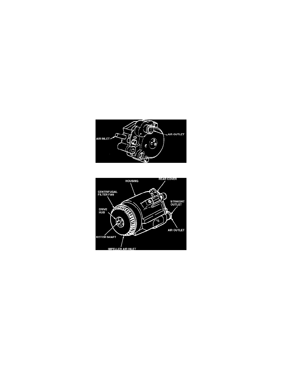
Figure 1 - 11-Cubic Inch Thermactor Air Supply Pump
Figure 2 - 19-Cubic Inch Thermactor Air Supply Pump
DESCRIPTION Passenger Cars and Light Trucks
The Air Supply Pump is a belt driven, positive displacement, vane type pump that provides air for the thermactor system. It is available in 11-cubic inch
and 19-cubic inch sizes, either of which may be driven with different pulley ratios for different applications. The 11-cubic inch pump (Figure 1) receives
its air through a remote filter attached to the air inlet nipple or through an impeller type centrifugal air filter fan. The 19-cubic inch pump (Figure 2) uses
an impeller type centrifugal air filter fan which separate dirt, dust, and other contaminants from the intake air by centrifugal force. The air supply pump
does not have a pressure relief valve, a function performed by the bypass valve. A description of the Thermactor System is in Section 10.
Functional Check
1.
Check belt tension, and adjust to specifications.
2.
Disconnect air supply hose from bypass control valve.
3.
The pump is operating satisfactorily if air flow is felt at the pump outlet and the flow increases as the engine speed is increased.
Do not pry on the pump to adjust belt. The aluminum housing is likely to collapse.