| In-vehicle Repair Special Tool(s) | | Support bar, engine 21-140 | | | Adaptor for 21-140 21-140-01 | | | Adaptor for 21-140 21-140-03 | | | Adaptor for 21-140 21-140-02 | Materials Name Specification Cable ties Sealer WSE-M4G323-A6 Removal All Vehicles | | -
General notes. - The positions of the engine mountings and engine roll restrictors are described looking from the transmission towards the engine.
- Owing to special model variants, some job steps do not apply to all vehicles. These are clearly marked in the text.
| | | -
Standard preparatory measures - Cut the cable ties where necessary and renew them on installation.
| Vehicles with 2,0 engine | | -
Remove the heat shield. - Detach the coolant hose from the bracket.
- Unscrew the upper bolts and remove the coolant hose bracket.
- Withdraw the engine oil dipstick.
- Remove the lower bolts.
| | | -
Detach the heat shield (1,6 and 1,8 engine). - Undo the upper bolts.
- Undo the lower bolts.
- Withdraw the engine oil dipstick.
| All vehicles | | -
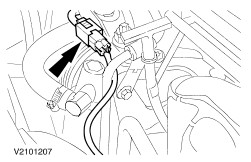
Disconnect the heated oxygen sensor (HO2S) plug. | | | -
Detach the catalytic converter from the exhaust manifold (2,0 engine shown). | | | -
Attach the special tools. | | | -
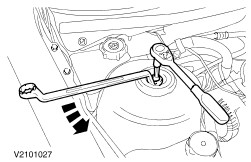
NOTE:Prevent the piston rod from moving using an Allen key. Undo the right-hand suspension strut nuts by five turns. | | | -
Detach the engine undershield (nine bolts). | | | -
Detach the right-hand lower wheelhouse cover (front wheel shown). | | | -
Remove the catalytic converter. - Unscrew the bolts.
- Unhook it from the rubber mountings.
| | | -
Detach the right-hand suspension lower arm ball joint from the spindle carrier (shown without wheel). | Vehicles with manual transmission | | -
Remove the center bolt for the right-hand engine roll restrictor. | Vehicles with automatic transmission | | -
Remove the center bolt for the right-hand engine roll restrictor. | | | -
Remove the center bolt for the left-hand engine roll restrictor. | | | -
Detach the coolant pipe bracket from the oil pan. | | | -
Drain off the engine oil. - Tighten the oil drain plug with new oil seal to 25 Nm.
| | | -
Detach the coolant expansion tank and place it to one side. | | | -
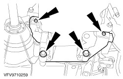
Detach the front engine support bracket from the engine mounting. | | | -
NOTE:Measurement points: Hole and upper face studs on front engine mounting bracket. Raise the engine 70 to 75 mm. | | | -
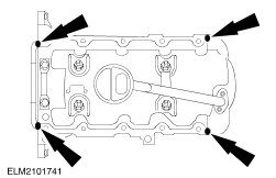
Remove the oil pan bolts from the clutch housing and detach the intermediate plate. | Installation All Vehicles | | -
NOTE:Use a silicone gasket and sealer. Apply sealer to the cylinder block mating face intersections. | | | -
Attach the oil pan. - Tighten the bolts in two stages.
| | | -
Attach the oil pan (continued). - Attach the intermediate plate.
- Press the oil pan flush against the clutch housing and tighten the bolts.
| | | -
Attach the oil pan (continued). | | | -
NOTE:Lower the vehicle carefully to avoid damaging the engine roll restrictor. Lower the vehicle. | | | -
Attach the front engine support bracket to the engine mounting. | | | -
Fit the coolant expansion tank. | | | -
Detach the special tools. | | | -
Attach the coolant pipe bracket to the oil pan. | Vehicles with automatic transmission | | -
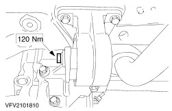
NOTE:The hole in the engine roll restrictor must line up with the hole in the bracket. If necessary, center as described in the following steps. Tighten the center bolt for the right-hand engine roll restrictor. | Vehicles with manual transmission | | -
NOTE:The hole in the engine roll restrictor must line up with the hole in the bracket. If necessary, center as described in the following steps. Tighten the center bolt for the right-hand engine roll restrictor. | | | -
NOTE:The hole in the engine roll restrictor must line up with the hole in the bracket. If necessary, center as described in the following steps. Tighten the center bolt for the left-hand engine roll restrictor. | Vehicles with automatic transmission | | -
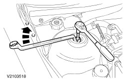
Center the right-hand engine roll restrictor. - Detach the vibration damper.
- Detach the vibration damper bracket.
| Vehicles with automatic transmission | | -
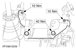
Center the right-hand engine roll restrictor (continued). - Undo the bolts of the engine roll restrictor bracket, re-tighten engine roll restrictor and bolts.
- Tighten the center bolt for the engine roll restrictor.
| Vehicles with automatic transmission | | -
Center the right-hand engine roll restrictor (continued). - Attach the vibration damper bracket.
- Attach the vibration damper.
| Vehicles with manual transmission | | -
Center the right-hand engine roll restrictor. - Undo the bolts of the engine roll restrictor bracket, align the engine roll restrictor and re-tighten the bolts.
- Tighten the center bolt for the engine roll restrictor.
| | | -
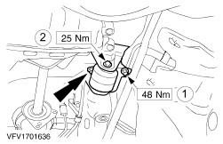
Center the left-hand engine roll restrictor. - Undo the nuts for the engine roll restrictor bracket, center the engine roll restrictor and re-tighten the nuts for the engine roll restrictor bracket.
- Tighten the center bolt for the engine roll restrictor.
| | | -
Attach the right-hand suspension lower arm ball joint to the spindle carrier (shown without wheel). | | | -
Install the catalytic converter. - Hook into the rubber insulators.
- Fit the bolts.
| | | -
Install the right-hand lower wheelhouse cover (shown with front wheel removed). | | | -
Attach the engine undershield (nine bolts). | | | -
NOTE:Prevent the piston rod from moving using an Allen key. Tighten the suspension strut lock nut. | | | -
Tighten the suspension strut lock nut (continued). | | | -
Attach the catalytic converter to the exhaust manifold (2,0 engine shown). | Vehicles with 2,0 engine | | -
NOTE:The upper bolts also secure the coolant hose bracket and oil dipstick bracket. Fit the heat shield. - Fit the lower bolts.
- Insert the dipstick.
- Screw in the upper bolts.
- Attach the coolant hose to the bracket.
| All vehicles | | -
Fit the heat shield. - Fit the lower bolts.
- Screw in the upper bolts.
| | |