| Assembly Special Tool(s) | | Universal flange holding wrench 15-030A | | | Aligner, clutch disk 16-067 | | | Installer, oil seal 21009B | | | Installer, oil seal 21-093A | | | Locking tool, flywheel 21-135 | | | Installer, oil seal 21-141 | | | Timing tool, camshaft alignment 21-162B | | | Socket, cylinder head bolts 21-167 | | | Angle gauge, bolt tightening 21-540 | General Equipment Piston ring compressor Assembly stand Assembly stand Steel straightedge Workshop hoist Materials Name Specification M10x70 bolt Never Seeze ESE-M1244-A Sealer ESK-M4G269-A Sealer WSE-M4G323-A4 Engine Oil WSS-M2C912-A1 Assembly | | -
Preparatory operations - Clean all the mating faces and reusable parts thoroughly and inspect them for damage.
| | | -
NOTE:Use new piston cooling oil splash nozzles. Fit the piston cooling oil splash nozzles and the blanking plugs. | | | -
NOTE:Main bearing shells of different thicknesses are fitted, which can also be used in servicing. Sizes of crankshaft main bearing shells. - Available sizes:
1. Size A: 2,152 - 2,145 mm (green) 2. Size B: 2,147 - 2,140 mm (brown) 3. Size C: 2,142 - 2,135 mm (yellow) 4. Size D: 2,137 - 2,130 mm (blue) | | | -
NOTE:Use bearing shells of size "B" or "C" (refer to step ). - Select the bearing shell according to step to obtain a bearing clearance of 0,020 - 0,040 mm.
| | | -
NOTE:The bearing cap numbering starts at the timing belt end, to which the arrows also point. NOTE:Use studs for bearings '2' and '4'. Fit the crankshaft. - Lubricate the main bearing journals and bearing shells with engine oil.
- Fit the crankshaft main bearing caps with their associated bearing shells.
| | | -
NOTE:The connecting rod numbering starts at the timing belt end. The arrow on the piston crown points towards the timing belt end. Fit the pistons. - Lubricate the pistons and cylinder liners with engine oil .
- Distribute the piston ring gaps uniformly around the circumference - this also applies to the elements of the oil scraper ring.
- Press pistons 1 and 4 into the cylinders using the handle of a hammer. The big-end bearing journal must be at BDC.
- Check the bearing shells are clean and dry and fit them in the associated connecting rods and bearing caps.
- Turn the crankshaft through 180 degrees and fit pistons 2 and 3.
| | | -
CAUTION:Only use new bolts. NOTE:The connecting rods and big-end bearing caps have the same numbering. Install the bearing caps. - Lubricate the bearing shells and journals with engine oil.
- Fit the appropriate big-end bearing caps and bearing shells and torque them down.
| | | -
Install the oil pump. - Locate the oil pump in position.
- Align the oil pump rotor with the recesses in the crankshaft.
- Screw in the bolts finger tight.
- Align the oil pump so that the mating face of the oil pump housing is 0,3 - 0,8 mm below the cylinder block.
- Tighten the bolts.
| | | -
Install the oil intake pipe and the oil baffle plate. - Install the oil intake pipe with a new gasket.
- Install the oil baffle plate with the oil intake pipe bracket.
| | | -
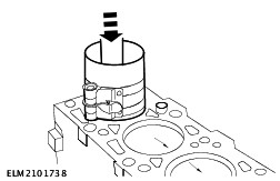
Fit the oil pump seal. - Draw in the new oil seal with the installer and the bolt of the crankshaft pulley.
| | | -
Fit the coolant pump with a new gasket. | | | -
Fit the rear oil seal carrier and the bracket of the CKP sensor. - Locate the oil seal carrier in position with a new gasket and screw in the bolts finger tight.
- Align the oil seal carrier so that the mating face of the oil seal carrier is 0,3 - 0,8 mm below the cylinder block.
- Tighten the four bolts.
- Fit the CKP sensor bracket.
| | | -
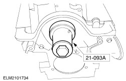
Fit the oil seal in the oil seal carrier. - Push in the radial oil seal using the special tool and two flywheel/drive plate bolts.
| | | -
NOTE:The oil pan bolts must be tightened within 10 minutes of applying the sealer. Apply sealer to the cylinder block mating face intersections. | | | -
Align the oil pan. - Locate the sump in position with a new gasket and screw the bolts in finger tight.
- Align the oil pan using a steel straightedge so that the cylinder block and oil pan are level.
| | | -
Secure the oil pan. - Tighten the ten oil pan bolts.
- Check that the oil pan is flush as in the previous step. If necessary, use spacer sleeves to remove any step.
| | | -
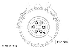
Fit the flywheel/drive plate. - Locate the flywheel in position and tighten the bolts finger tight.
- Immobilise the flywheel with Special Tool 21-135.
| | | -
Center the clutch disk on the clutch pressure plate. | | | -
Install the clutch. - Locate the clutch pressure plate in position with the centered clutch disk.
- Screw in the bolts uniformly two turns each and then to the correct torque, working diagonally.
- Remove the special tool.
| | | -
CAUTION:Bring the piston of cylinder no. 1 to a point approx. 20 mm before TDC to avoid damage when fitting the cylinder head. Fit the crankshaft timing pulley. - Thrust plate.
- Timing pulley.
| | | -
NOTE:'TOP' mark and gasket identification. Fit the cylinder head. - Check that the locating bushes are seated correctly.
- Fit a new cylinder head gasket.
| | | -
Pre-tighten the cylinder head bolts. - Screw in new, unoiled cylinder head bolts.
- Fit cylinder head bolts in two stages in accordance with the tightening sequence.
| | | -
CAUTION:The cylinder head bolts must not be retorqued. Tighten the cylinder head bolts, Stage 3. - Tighten the cylinder head bolts in the indicated sequence.
- Lubricate the hydraulic tappets with engine oil and proceed according to the removal sequence.
| | | -
NOTE:The camshafts are marked. The inlet camshaft has an additional cam for the CMP sensor at the end of the shaft. Fit the camshafts. - Apply sealer to the cylinder head / bearing cap mating face at the timing belt end.
| | | -
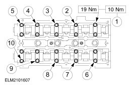
NOTE:The numbering starts at '0' on the exhaust side and faces outwards. Fit the camshaft bearing caps. - Lubricate the camshaft bearing surfaces and the bearing surfaces in the cylinder head with engine oil.
| | | -
Fit the camshaft bearing caps. - Screw in the bolts in pairs in the indicated sequence half a turn at a time.
- Repeat this until the bearing caps are in contact with the cylinder head.
- Tighten the bolts in pairs in the indicated sequence.
| | | -
NOTE:The camshaft timing pulleys must be able to turn freely on the camshafts; do not tighten the bolts. Fit the camshaft seals. - Lubricate the camshafts and the sealing lip of the oil seals with engine oil.
- Draw in the new oil seals using the special tool, a washer and an M10x70 bolt .
| | | -
NOTE:The camshaft timing pulleys must be able to turn freely on the camshafts; do not tighten the bolts. Install the camshaft timing belts. | | | -
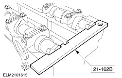
Align the camshafts. - Insert the special tool into the camshafts.
| | | -
CAUTION:Install the retaining stud and spring if not present. Tension the pulley against the spring pressure. - Install the spring retaining stud (if not present).
- Hook the timing belt tensioner spring in place (if not present).
- Tension the pulley against the spring by turning it clockwise with an Allen key and secure it.
| | | -
Turn the crankshaft to TDC. - For greater accuracy, extend the mark on the oil pan with a small strip of metal (25 mm wide) or similar.
| | | -
CAUTION:Use a new timing belt. CAUTION:Do not kink the timing belt (bend diameter must not be less than 35 mm). NOTE:Turn the camshaft timing pulleys so that the timing belt engages correctly in all the timing pulleys. NOTE:The tension side of the timing belt (between the crankshaft timing pulley and the camshaft timing pulley) must be taut. Lay the new timing belt in place. - Check that the crankshaft is at TDC.
- Fit the timing belt, working in an counter-clockwise direction, starting from the crankshaft timing pulley.
- Slacken the bolt of the tensioning pulley. The timing belt will be tensioned by the spring.
| | | -
Secure the timing belt tensioner. - Secure the timing belt tensioner pulley.
| CAUTION:Do not tighten the camshaft timing pulley bolts using Special Tool 21-162B; use Special Tool 15-030A to prevent movement. | | -
NOTE:The crankshaft must be at TDC. Tighten the bolts of the camshaft timing pulleys. - Remove Special Tool 21-162B.
| | | -
Turn the crankshaft two turns clockwise as far as the TDC position. | | | -
Secure the timing belt tensioner. - Secure the timing belt tensioner pulley.
- Check that the crankshaft and camshafts are at TDC.
| | | -
CAUTION:Do not remove or tighten the camshaft timing pulley bolts using Special Tool 21-162B; use Special Tool 15-030A to prevent movement. NOTE:The crankshaft must remain in the TDC position. Special tool 21-162B cannot be inserted. - Slacken the camshaft timing pulley of the camshaft concerned. Hold the pulley with Special Tool 15-030A.
- Turn the camshaft until Special Tool 21-162B can be inserted.
- Tighten the bolt of the camshaft timing pulley.
- Turn the crankshaft another two turns in the clockwise direction as far as the TDC position and check the alignment of the camshaft.
| | | -
CAUTION:Use a blunt object to apply the silicone grease (e.g. a plastic cable tie) to avoid damaging the spark plug connector seal. CAUTION:Push on the spark plug connectors in a straight line with the axis of the spark plug. NOTE:Coat the inside of the spark plug connectors to a depth of 5-10 mm with silicone grease. NOTE:Use a new cylinder head cover gasket. Install the spark plugs and cylinder head cover. - Screw in the spark plugs and tighten them.
- Fit ten bolts.
- Connect the HT leads to the spark plugs.
| | | -
Fit the timing belt covers. - Make sure that the middle cover is seated correctly in the lower cover.
| | | -
Immobilise the flywheel with Special Tool 21-135. | | | -
Attach the coolant pump belt pulley and the crankshaft pulley/vibration damper. | | | -
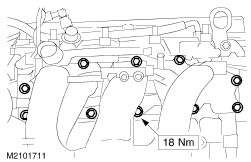
Connect the PCV. - Screw in the three bolts.
- PCV pipe
| | | -
CAUTION:If the stud came out when the engine lifting eye was removed, first fit the stud and tighten it to 6 Nm, and then secure the engine lifting eye with the nut. Fit the exhaust manifold, ignition coil and thermostat housing. - Detach Special Tool 21-135 from the flywheel/drive plate.
- Engine lifting eye
- Fit the bracket of the power steering pump/air conditioning compressor (eight bolts).
- Fit the exhaust manifold (eight nuts)
- Fit the ignition coil (three bolts)
- Thermostat housing
- Attach the coolant hose to the coolant pump
| | | -
Fit the intake manifold. - Attach the injector wiring harness (two bolts).
| | | -
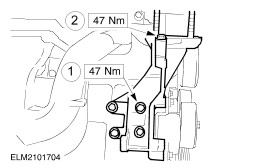
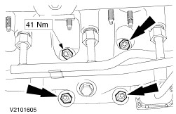
Fit the generator bracket. - Fit the bolts.
- Engine lifting eye
| | | -
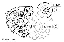
Fit the generator and the idler pulley. - Drive belt idler pulley
- Generator
| | | -
Attach the cable guide to the intake manifold. | | | -
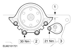
Fit the center bearing bracket and the oil pressure switch. - Oil pressure switch
- Tighten the three bolts.
| | | -
Connect the plugs and fit the filter of the pulse air system. - Plug of CKP sensor.
- Plug of coolant temperature sender unit.
| | | -
Connect the plugs. - Ignition coil (EI)
- Radio interference suppressor.
- ECT sensor.
| | | -
Connect the plugs and the generator. - Plug of engine main wiring harness.
- TP sensor.
- CMP sensor.
- Connect the generator.
| | | -
Attach the catalytic converter to the exhaust manifold (2,0 engine shown). | | | -
CAUTION:Support the engine with wooden wedges and secure it with clamping straps. | | | -
Install the oil filter. - Lubricate the gasket with engine oil.
- Tighten it half to three-quarters of a turn after it touches the mating face.
| | |