| Disassembly Special Tool(s) | | Universal Flange Holding Wrench 205-072 (15-030 A) | | | Remover, Seal 303-112 (21-051) | | | Remover, Crankshaft Seal 303-293 (21-143) | | | Remover, Crankshaft Vibration Damper 303-338 (21-153 B) | | | Adapter for 303-338 303-338-02 (21-153 A02) | | | Remover/Installer, Hose Clamp 303-397 (24-003) | | | Mounting Bracket for 303-435 303-435-06 (21-031 B) | | | Mounting Plate for 303-435-06 303-435-11A (21-146 C) | | | Socket, Spark Plug 303-499 (21-202) | General Equipment Disassembly All vehicles | | -
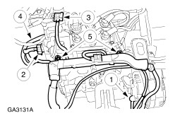
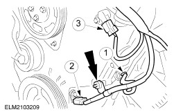
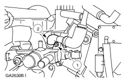
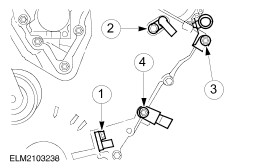
Disconnect the exhaust gas recirculation (EGR) pipe from the EGR valve. - Detach the hoses.
- Unscrew the pipe.
| | | -
Remove the right-hand exhaust manifold. | | | -
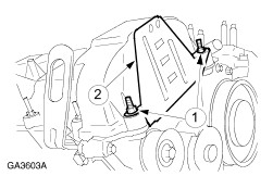
Remove the intermediate driveshaft bracket. | | | -
Attach the special tool to the engine. | | | -
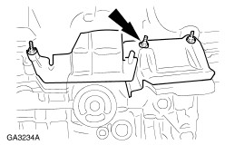
Install the mounting bracket to the mounting plate. | | | -
Mount the engine on the mounting stand. | | | -
Disconnect off the plugs and detach the wiring harness. - Generator cable.
- Differential pressure feedback EGR (DPFE) plug.
- Electronic vacuum regulator.
- ECT sensor on coolant distribution pipe.
- Detach the wiring rail.
| | | -
Disconnect the intake manifold runner control (IMRC) cable. | | | -
Remove the IMRC actuator. - Disconnect the IMRC multiplug.
- Unscrew the bolts.
| | | -
Disconnect the spark plug connectors. | | | -
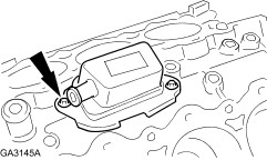
Detach the EI coil with the high tension leads and the spark plug connectors. - Disconnect the EI ignition coil multiplug.
- Detach the ground cable.
- Detach the condenser.
- Remove the remaining bolts and the EI coil.
| | | -
Disconnect the vacuum hoses. - From the upper intake manifold.
- From the electronic vacuum regulator.
- From the fuel pressure regulator.
- From the DPFE.
- From the EGR valve.
| | | -
Pull off the hoses and the electrical plugs. - Throttle position (TP) sensor plug.
- Positive crankcase ventilation hose.
- Idle air control valve (IAC valve) plug.
| | | -
Remove the upper intake manifold. | | | -
Disconnect the heated oxygen sensor (H02S) plug. | | | -
Disconnect the plugs. - Oil pressure switch.
- Crankshaft position (CKP) sensor.
- Camshaft position (CMP) sensor.
- Unclip the wiring harness.
| | | -
Detach the fuel injection system wiring harness. - Pull off the engine coolant temperature sensor (ECT sensor) plug.
- Pull off the EGR back pressure transducer plug.
- Pull off the fuel injector plugs.
| | | -
Remove the lower intake manifold. | | | -
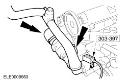
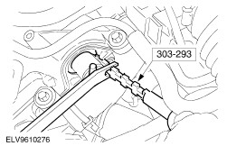
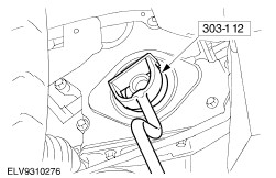
Using the special tool, remove the thermostat housing with the coolant hoses. | | | -
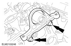
Detach the coolant distribution pipe, the engine lifting eye and the oil dipstick. - Unscrew the nuts.
- Detach the left-hand engine lifting eye.
- Withdraw the engine oil dipstick.
| | | -
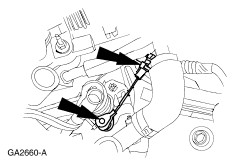
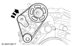
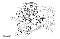
Remove the coolant pump drivebelt. - Rotate the belt tensioner clockwise to relieve tension on the drivebelt.
| | | -
Remove the hose and the positive crankcase ventilation valve. - Unscrew the nut.
- Detach the hose and the positive crankcase ventilation valve.
| | | -
Remove the coolant connecting pipe. | | | -
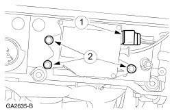
Remove the coolant pump. - Unscrew the bolts.
- Disconnect the coolant hose.
- Detach the coolant hose from the oil cooler.
| Vehicles with manual transaxle | | -
Remove the clutch disc and pressure plate. For additional information, refer to Section 308-01 Clutch. | | | -
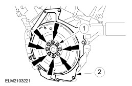
Remove the flywheel. - Remove the flywheel retaining bolts.
- Remove the adapter plate.
| Vehicles with automatic transaxle | | -
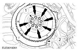
Remove the flexplate. - Remove the flexplate retaining bolts.
- Remove the adapter plate.
| All vehicles | | -
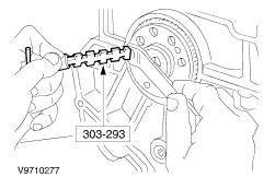
CAUTION:Do not scratch or damage the seal sealing surfaces on the crankshaft and cylinder block. Use a 0,25 mm brass or copper shim to protect the sealing surface. CAUTION:Only insert the special tool by hand. Remove the crankshaft rear seal. | | | -
Remove the generator. - Remove the bracket bolt.
- Remove the generator bolts.
| | | -
Remove the generator bracket. | | | -
Remove the left-hand exhaust manifold. | | | -
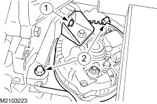
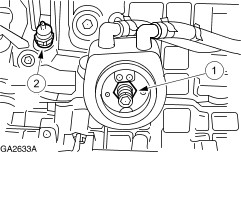
Remove the oil cooler and the oil pressure switch. - Unscrew the bolt and remove the oil cooler.
- Remove the oil pressure switch.
| | | -
Remove the studs and take off the oil pan heat shields. | | | -
Remove the oil pan. - Check the oil pan and the cylinder block for damage.
| | | -
Remove the wiring harness retaining plate. - Unscrew the bolts.
- Take off the retaining plate.
| | | -
Detach the right-hand engine lifting eye. - Remove the bolt.
- Take off the engine lifting eye.
| | | -
NOTE:Slackening sequence. Remove the valve covers. | | | -
Remove the camshaft pulley. | | | -
CAUTION:Only insert the special tool by hand. Using the special tool, remove the camshaft seal. | | | -
CAUTION:Protect the camshaft when removing the seal carrier. Remove the camshaft seal carrier. | | | -
Remove the power steering pump pulley (four bolts). | | | -
Remove the power steering pump and bracket. | | | -
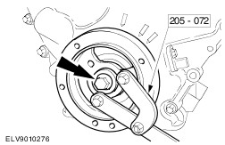
Using the special tool, remove the crankshaft pulley retaining bolt. | | | -
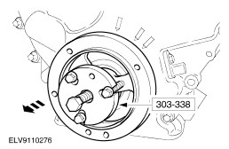
Using the special tool, remove the crankshaft pulley. | | | -
Remove the sensors and wiring brackets. - CKP sensor.
- CMP sensor.
- Wiring bracket.
- Wiring bracket.
| | | -
Remove the timing chain cover. | | | -
CAUTION:Protect the surface of the crankshaft while removing the seal. Using the special tool, remove the crankshaft front seal (engine shown installed). | | | -
Position the crankshaft. - Remove the CKP sensor pulse ring.
- Screw in the crankshaft pulley/vibration damper bolt and turn the crankshaft clockwise until the Woodruff key is in the 3 o'clock position. Undo the bolt.
| | | -
Install the crankshaft pulley retaining bolt and washer. | | | -
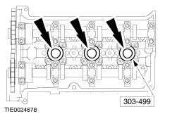
Using the special tool, remove the right-hand spark plugs. | | | -
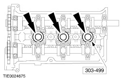
Using the special tool, remove the left-hand spark plugs. | | | -
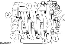
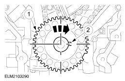
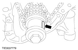
Rotate the crankshaft in a clockwise direction to position number one cylinder at top dead center (TDC) with the crankshaft keyway at the 11 o'clock position. - If the camshafts are not positioned as shown, rotate the crankshaft one complete revolution.
| | | -
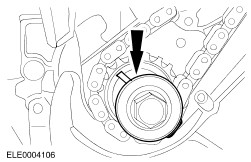
Rotate the crankshaft in a clockwise direction to position the crankshaft keyway at the 3 o'clock position. - The right-hand camshafts will be in the neutral position.
| | | -
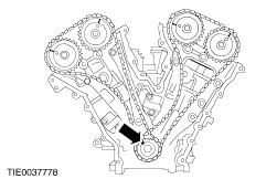
NOTE:Mark the position of all timing chain tensioner components to make sure they are assembled in their original positions. Remove the right-hand timing chain tensioner and timing chain tensioner arm. - Remove the bolts.
- Remove the timing chain tensioner.
- Remove the timing chain tensioner arm.
| | | -
Remove the right-hand timing chain. - Remove the right-hand timing chain guide.
- Remove the right-hand timing chain.
| | | -
CAUTION:The cylinder head and the camshaft bearing caps are numbered and marked for left-hand and right-hand cylinder heads. CAUTION:Remove camshaft bearing thrust caps No. 1R and 5R first. Do not loosen any other retaining bolts until the thrust caps are removed. NOTE:Camshaft bearing caps are dowelled to the cylinder head. If necessary, use a plastic mallet to loosen the caps. NOTE:Loosen the retaining bolts and bearing caps in the indicated sequence in several passes to allow the camshafts to gradually rise from the cylinder head. NOTE:If the cam followers and valve tappets are to be re-used, mark their position to make sure they are assembled in the original location. Remove the right-hand cylinder head camshafts. - Remove the cam followers.
- Remove the valve tappets.
| | | -
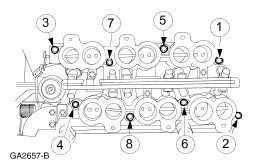
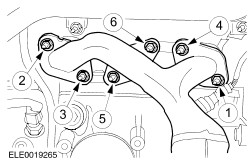
CAUTION:Remove the right-hand cylinder head bolts in the sequence shown in several passes. Remove the right-hand cylinder head. - Discard the cylinder head bolts, washers and gasket.
| | | -
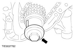
Rotate the crankshaft in a clockwise direction approximately 600 degrees and position the crankshaft keyway at the 11 o'clock position. | | | -
Remove the crankshaft pulley retaining bolt and washer. | | | -
NOTE:Mark the position of all timing chain tensioner components to make sure they are assembled in their original positions. Remove the left-hand timing chain tensioner and timing chain tensioner arm. - Remove the bolts.
- Remove the timing chain tensioner.
- Remove the timing chain tensioner arm.
| | | -
Remove the left-hand timing chain. - Remove the left-hand timing chain guide.
- Remove the left-hand timing chain.
| | | -
CAUTION:The cylinder head and the camshaft bearing caps are numbered and marked for left-hand and right-hand cylinder heads. CAUTION:Remove camshaft bearing thrust caps No. 1L and 5L first. Do not loosen any other retaining bolts until the thrust caps are removed. NOTE:Loosen the retaining bolts and bearing caps in the sequence shown in several passes to allow the camshafts to gradually rise from the cylinder head. NOTE:Camshaft bearing caps are dowelled to the cylinder head. If necessary, use a plastic mallet to loosen the caps. NOTE:If the cam followers and valve tappets are to be re-used, mark their position to make sure they are assembled in the original location. Remove the left-hand camshafts. - Remove the cam followers.
- Remove the valve tappets.
| | | -
CAUTION:Remove the left-hand cylinder head bolts in the sequence shown in several passes. Remove the left-hand cylinder head. - Discard the cylinder head bolts, washers and gasket.
| | | -
Remove the bracket for the power steering pump. | | | -
Remove the oil separator. | | | -
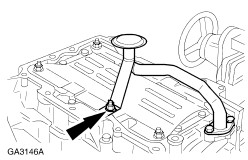
Remove the oil intake pipe. | | | -
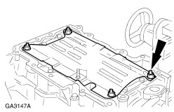
Remove the oil pan baffle. | |