| In-vehicle Repair Special Tool(s) | | Installer, Oil Seal 303-039 (21009B) | | | Lifting Bracket, Engine 303-122 (21068A) | | | Alignment Plate, Camshaft 303-376 (21-162B) | | | Socket, Cylinder Head Bolts 303-392 (21167) | General Equipment Spatula Wooden support Workshop jack Workshop hoist Engine lifting eye (part no. 938F 17A084 AF) Materials Name Specification Sealer - Camshaft bearing cap WSK-M4G348-A5 Sealer remover WSK-M2G348-A4 Engine oil WSS-M2C912-A1 Silicone grease for spark plug connector seals A969-M1C171-A4 Never Seez Removal | | -
General Notes. - Request the radio keycode.
- Make a note of the pre-set radio stations.
- The position markings for the engine mountings and engine roll restrictors are described looking from the transmission towards the engine.
- Any steps which only apply to certain variants and not to all vehicles are clearly indicated.
- If necessary, unfasten cable ties and install new ones when reinstalling.
| | | -
Disconnect the battery ground cable.
For additional information, refer to: Batterie abklemmen (414-01 Batterie, Befestigung und Batteriekabel, General Procedures).
| | | -
Drain the coolant.
For additional information, refer to: Kühlsystem entleeren, mit Kühlmittel auffüllen und entlüften (303-03 Kühlsystem, General Procedures).
| | | -
Detach the pulley cover (if equipped). | | | -
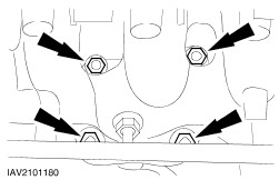
Unscrew the nuts and studs from the power steering pump bracket (shown from above with the heat shield removed). | | | -
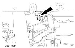
Disconnect the plug of the crankshaft position sensor (CKP sensor). | | | -
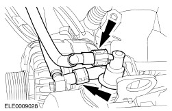
Detach the brake booster line from the intake manifold. - Release the quick release coupling and pull out the pipe.
| | | -
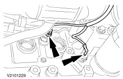
Disconnect the oil pressure switch plug and the knock sensor plug (KS) (if equipped). | | | -
Remove the intake pipe together with the air filter housing. - Disconnect the mass air flow (MAF) sensor plug (if equipped).
- Disconnect the intake air temperature (IAT) sensor multiplug (if equipped).
- Remove one bolt and two nuts.
| | | -
Remove the intake pipe together with the air filter housing. - Detach the positive crankcase ventilation (PCV) hose.
- Disconnect the intake hose.
- Pull out the air cleaner housing from the rubber bushes.
| | | -
NOTE:This step only applies to vehicles with liquid propane gas (LPG) drive. Detach the LPG fuel rail.
For additional information, refer to: Kraftstoffverteilerrohr (303-04E Kraftstoffsystem - Flüssiggas Propan (LPG), Removal and Installation).
| | | -
NOTE:This step only applies to vehicles with liquid propane gas (LPG) drive. Detach the bracket for the power steering line from the cylinder head. | | | -
NOTE:This step only applies to vehicles with liquid propane gas (LPG) drive. Install the engine lifting eye in place of the bracket for the power steering line. | | | -
Detach the cruise control cable (if equipped). - Cable from throttle valve
- Pull the cable out of the bush while gently moving it up and down.
- Press the bush out of the bracket.
| | | -
Detach the accelerator cable. - Pull off the plastic clip and lay the accelerator cable to one side.
| | | -
Release the fuel pressure.
For additional information, refer to: Druck - Kraftstoffsystem ablassen (310-00A Kraftstoffsystem - Allgemeine Informationen, General Procedures).
| | | -
WARNING:Do not smoke or carry lighted tobacco or open flame of any type when working on or near any fuel related components. Highly flammable vapors are always present and may ignite. Failure to observe these instructions can lead to personal injury. Disconnect the fuel lines. | | | -
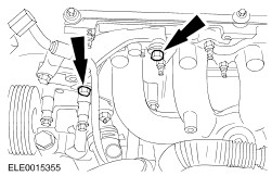
Disconnect the vacuum hoses and detach the connector. | | | -
Detach the wiring rail from the intake manifold. - Disconnect the positive cable at the fuse element and unclip the fuse element from the wiring rail (if equipped).
- Remove the three bolts.
- Cut the cable ties.
| | | -
Disconnect the EGR hoses (if equipped). | | | -
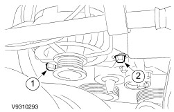
Disconnect the coolant hoses from the thermostat housing. | | | -
Detach the connector. - From the radio interference suppresser
| | | -
Disconnect the plug of the coolant temperature sender unit. | | | -
Remove the heat shield. - Unscrew the upper bolts.
- Remove the coolant hose bracket.
- Detach the bracket for the air conditioning pipe.
- Remove the lower retaining bolts.
| | | -
Detach the exhaust pipe from the exhaust manifold. | | | -
Detach the oil dipstick tube and the power steering fluid line bracket. | | | -
Detach the power steering reservoir (1 bolt). | | | -
Detach the coolant recovery tank. - Unclip the cruise control system cable from the coolant expansion tank.
- Lay the recovery tank to one side.
| | | -
Detach the bracket for the power steering pump. - Lay the bracket with the pump to one side.
| | | -
Remove the generator. - Loosen the bolt.
- Remove the bolt.
| | | -
Remove the upper bolt from the generator bracket. | | | -
Remove the timing belt.
For additional information, refer to: Zahnriemen (303-01D Motor - gebaut ab 05/1998 1.6L/1.8L/2.0L, In-vehicle Repair).
| | | -
Measure the valve clearance, if necessary.
For additional information, refer to: Ventilspiel (303-01D Motor - gebaut ab 05/1998 1.6L/1.8L/2.0L, General Procedures).
| | | -
Unscrew the bolts of the camshaft bearing caps evenly in several stages, two turns at a time. - Remove the valve tappets and lay them in order to one side.
| | | -
CAUTION:Mark the bolts to be reused with one or two punch marks. Bolts can be reused twice. Discard bolts as necessary. CAUTION:The cylinder head must cool down to ambient temperature before proceeding. Undo the cylinder head bolts. | | | -
Lift off the cylinder head. - Hook the special tool into the engine lifting eyes.
- Lift off the cylinder head using a workshop hoist and place it on clean wooden blocks.
| Installation | | -
Preparatory operations. - Thoroughly clean the threaded holes of the cylinder head bolts.
| | | -
Check the cylinder head for distortion.
For additional information, refer to: Ventilspiel (303-01D Motor - gebaut ab 05/1998 1.6L/1.8L/2.0L, General Procedures).
| | | -
Fabricate two locating studs as shown in the diagram. | | | -
CAUTION:The choice of cylinder head gasket depends on the number of the cast cylinder block. Lay a new cylinder head gasket on the cylinder block and position the cylinder head. - Cylinder block number
- Install a new cylinder head gasket.
- Insert the fabricated guide bolts.
- Check that the guide sleeves are correctly seated.
- Position the cylinder head on the cylinder block.
| | | -
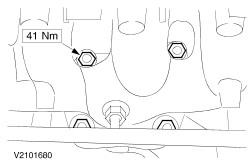
CAUTION:The cylinder head bolts must not be retightened. Tighten the cylinder head using Special Tool 303-9,956.80 mm three stages in the sequence indicated. - Stage 1: Tighten the bolts to 15 Nm.
- Stage 2: Tighten the bolts to 40 Nm.
- Stage 3: Tighten the bolts by 90°.
- Coat the tappets with engine oil and install them in the positions from which they were removed.
| | | -
Apply sealant to camshaft bearing caps nos. 0 and 5, in the areas shown. | | | -
Set the crankshaft to approx. 60 degrees before TDC. | | | -
NOTE:The identification numbers are located on the outside of the camshaft bearing caps. Lay the camshafts in place with none of the cams at full lift. - Lubricate the camshaft and camshaft bearing caps with engine oil .
| | | -
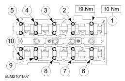
NOTE:Screw in the camshaft bearing cap bolts evenly, in the sequence shown, a half turn at a time and tighten them in two stages. Tighten the camshaft bearing cap bolts. | | | -
Install the camshaft oil seals. - Lubricate the camshafts and the sealing lip of the oil seals with engine oil .
- Draw in the new oil seals using the special tool, a washer and an M10x70 bolt.
| | | -
Turn the camshafts to ignition point on cylinder no. 1 and insert the special tool into the camshafts. | | | -
Install the timing belt.
For additional information, refer to: Zahnriemen (303-01D Motor - gebaut ab 05/1998 1.6L/1.8L/2.0L, In-vehicle Repair).
| | | -
Attach the bracket for the power steering pump. - Move the bracket with the power steering pump into the installation position.
- Screw in the upper bolts and tighten them to torque.
| | | -
Connect the vacuum hoses to the EGR valve (if equipped). | | | -
Attach the oil dipstick tube and the power steering fluid line bracket. | | | -
Attach the exhaust pipe to the exhaust manifold using a new gasket. | | | -
Install the upper generator bolt. | | | -
Raise the vehicle.
For additional information, refer to: Anheben mit Hebebühne (100-02 Fahrzeug anheben, Description and Operation).
| | | -
Install the studs and nuts of the bracket for the power steering pump (shown from above with the heat shield removed). | | | -
Connect the oil pressure switch and the KS plug (if equipped). | | | -
Attach the brake booster line to the exhaust manifold. | | | -
Install the heat shield. - Insert the oil dipstick tube, and position the coolant hose bracket and the engine lifting eye.
- Screw in the upper bolts.
- Attach the bracket to the air conditioning line.
- Install the lower retaining screws.
| | | -
Attach the power steering fluid reservoir. | | | -
Attach the pulley cover (if removed). | | | -
Connect the plug of the temperature gauge sender unit. | | | -
Connect the coolant hoses to the thermostat housing. | | | -
Attach the connectors. - To the radio interference suppression filter
| | | -
CAUTION:Do not bend the fuse element when tightening the nut, as this could cause it to break. Attach the cable guide to the intake manifold. - Clip the fuse element to the wiring rail and connect the positive cable to the fuse element (if equipped).
- Install the three bolts.
- Join the cable ties.
| | | -
Connect the vacuum hoses to the inlet manifold and connect the plug. | | | -
WARNING:Do not smoke or carry lighted tobacco or open flame of any type when working on or near any fuel related components. Highly flammable vapors are always present and may ignite. Failure to observe these instructions can lead to personal injury. Connect the fuel lines. | | | -
Attach the accelerator cable and adjust it. - Attach the cable in the bracket and slide on the plastic clip.
- Pull the clip off the accelerator cable.
- Pull the inner cable a few clicks out from the outer cable.
- Fully depress the accelerator pedal once and slide the clip back on.
- Check that the throttle plate opens fully when the accelerator pedal is depressed. If not, repeat the adjustment procedure.
| | | -
Attach the cruise control cable. - Press the bush into the bracket.
NOTE:An audible click indicates proper engagement. - Slide the cable into the bush.
- Attach the cable to the throttle valve.
| | | -
NOTE:This step only applies to vehicles with liquid propane gas (LPG) drive. Remove the engine lifting eye. | | | -
NOTE:This step only applies to vehicles with liquid propane gas (LPG) drive. Attach the bracket for the power steering line. | | | -
NOTE:This step only applies to vehicles with liquid propane gas (LPG) drive. Attach the LPG fuel rail.
For additional information, refer to: Kraftstoffverteilerrohr (303-04E Kraftstoffsystem - Flüssiggas Propan (LPG), Removal and Installation).
| | | -
Install the intake pipe together with the air filter housing. - Press the air cleaner into the rubber bushes.
- Attach the positive crankcase ventilation hose.
- Attach the intake hose.
| | | -
Install the intake pipe. - Connect the plug of the MAF sensor.
- Connect the IAT sensor plug.
- Install a bolt and the two nuts.
| | | -
Top up with coolant.
For additional information, refer to: Kühlsystem entleeren, mit Kühlmittel auffüllen und entlüften (303-03 Kühlsystem, General Procedures).
| | | -
Connect the battery ground cable.
For additional information, refer to: Batterie abklemmen (414-01 Batterie, Befestigung und Batteriekabel, General Procedures).
| | | -
Standard finishing operations. - Check fluid levels and correct if necessary.
- Check the routing of the vacuum hoses and wiring and secure them with cable ties.
- Reprogram the pre-set radio stations.
- Carry out a road test to enable the PCM to collect data.
- Check the fluid levels again and correct as necessary.
| | |