| PINPOINT TEST A : THE HORN DOES NOT SOUND |
| TEST CONDITIONS | DETAILS/RESULTS/ACTIONS |
| A1: CHECK THE OPERATION OF THE HORN RELAY |
| | 1 Press the horn switch and listen for the horn relay clicking. |
| | Does the horn relay click when the horn switch is pressed? Yes No |
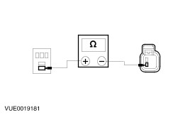
| A2: CHECK THE HORN SWITCH OPERATION |
| | 1 Disconnect Horn Relay C903. |
| | 2 Press and hold the horn switch. |
| | 3 Measure the resistance between horn relay C903 pin 1, circuit 31S-GJ7 (BK), harness side and ground. |
| | 4 Release the horn switch. |
| | Is the resistance less than 5 ohms? Yes No |
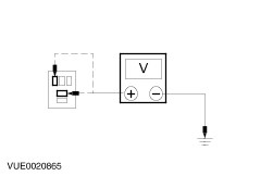
| A3: CHECK FOR VOLTAGE AT HORN RELAY |
| | 1 Measure the voltage between horn relay C903 pin 2, circuit 30-GJ7 (RD), harness side and ground; and between the horn relay C903 pin 5, circuit 30-GJ8 (RD), harness side and ground. |
| | Are the voltages greater than 10 volts? Yes CARRY OUT the relay Component Test. REFER to the wiring diagrams. INSTALL a new horn relay as necessary. TEST the system for normal operation. No INSTALL a new battery junction box (BJB). TEST the system for normal operation. |
| A4: CHECK CIRCUIT 31S-GJ7 (BK/BU) FOR SHORT TO GROUND |
WARNING:To deactivate the air bag module, refer to the procedure in Section 501-20B for the correct air bag module deactivation procedure. Failure to follow this instruction may result in personal injury. |
| | 1 |
| | 2 Disconnect Clock Spring C413. |
| | 3 Measure the resistance between clock spring C413 pin 4, circuit 31S-GJ7 (BK/BU), harness side and ground. |
| | Is the resistance less than 5 ohms? Yes REPAIR the circuit. TEST the system for normal operation. No |
| A5: CHECK THE CLOCK SPRING |
| | 1 Disconnect Horn Switch C4. |
| | 2 Measure the resistance between horn switch C4 pin 1, harness side and ground. |
| | Is the resistance greater than 10,000 ohms? Yes No |
| A6: CHECK THE HORN SWITCH |
| | 1 Disconnect Horn Switch C5. |
| | 2 Measure the resistance between horn switch C5 pin 1, component side and ground. |
| | Is the resistance greater than 10,000 ohms? Yes INSTALL a new horn switch. REFER to Horn Switch in this section. TEST the system for normal operation. No |
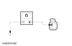
| A7: CHECK GROUND CIRCUIT 31-GJ9 (BK) |
| | 1 Measure the resistance between clock spring C413 pin 3, circuit 31-GJ9 (BK), harness side and ground. |
| | Is the resistance less than 5 ohms? Yes No REPAIR the circuit. TEST the system for normal operation. |
| A8: CHECK THE HORN GROUND CIRCUIT |
| | 1 Disconnect Horn Relay C903. |
| | 2 Measure the resistance between horn relay C903 pin 3, circuit 29S-GJ6 (OG/YE), harness side and ground. |
| | Is the resistance between 0.5 and 4 ohms? Yes No |
| A9: CHECK VOLTAGE AT HORN RELAY |
| | 1 Measure the voltage between horn relay C903 pin 5, circuit 30-GJ8 (RD), harness side and ground. |
| | Is the voltage greater than 10 volts? Yes CARRY OUT the relay Component Test. REFER to the wiring diagrams. INSTALL a new horn relay as necessary. TEST the system for normal operation. No INSTALL a new battery junction box (BJB). TEST the system for normal operation. |
| A10: CHECK CIRCUIT 29S-GJ6 (OG/YE) FOR OPEN |
| | 1 Disconnect Horn C151. |
| | 2 Measure the resistance between horn relay C903 pin 3, circuit 29S-GJ6 (OG/YE), harness side and the horn C151 pin 2, harness side. |
| | Is the resistance less than 5 ohms? Yes No REPAIR the circuit. TEST the system for normal operation. |
| A11: CHECK THE HORN GROUND CIRCUIT |
| | 1 Measure the resistance between horn C151 pin 1, circuit 31-GJ6 (BK), harness side and ground. |
| | Is the resistance less than 5 ohms? Yes INSTALL a new horn. TEST the system for normal operation. No REPAIR circuit 31-GJ6 (BK). TEST the system for normal operation. |