| Diagnosis and Testing For Wiring Schematics and Connector Information, refer to the Wiring Diagram Cell 501-10. Principals of Operation The vehicle is equipped with a bidirectional power operated driver seat as standard, and as an option for the passenger seat, where the power function is limited to seat height adjustment only. Vehicles equipped with the full eight-way power seat functionality are controlled by a single multifunction control switch. In each case the switch is mounted onto the seat base panel within easy reach of the driver. Seats with power height adjustment retain manual adjustment controls to attain seat adjustment. The bidirectional switch controls the operation of a single motor which depending on switch operation will either raise or lower the seat height through a series of mechanical linkages. Seats with full eight-way adjustment are able to adjust the seat position through any one of four different motors. Each seat function is controlled by a single multifunction switch, which in turn controls the operation of the bidirectional motor of the selected adjustment feature to achieve: - Vertical adjustment of the front of the seat cushion;
- Vertical adjustment of the rear of the seat cushion;
- Horizontal seat movement along the seat track through a mechanical worm drive;
- Seat backrest position adjustment of the backrest rake angle.
Inspection and Verification - Verify the customer concern.
- Visually inspect for obvious signs of mechanical or electrical damage.
Visual Inspection Chart | Mechanical | Electrical | - Damaged switch(es).
- Obstruction of ventilated seat air intake.
| - Fuse(s).
- Wiring harness.
- Electrical connector(s).
- Motor(s).
- Switch(es).
| - If an obvious cause for an observed or reported concern is found, correct the cause (if possible) before proceeding to the next step.
- If the cause is not visually evident, verify the symptom and refer to the Symptom Chart.
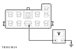
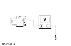
Symptom Chart Symptom Chart | Symptom | Possible Sources | Action | | The power seat is inoperative | * Seat control switch. | * CARRY OUT the Seat Control Switch Component Test. REFER to the Wiring Diagrams. | | * Circuit(s). * Motor(s). | * | | The power seat does not move horizontally | * Seat control switch. | * CARRY OUT the Seat Control Switch Component Test. REFER to the Wiring Diagrams. | | * Circuit(s). * Motor(s). | * | | The power seat does not move vertically | * Seat control switch. | * CARRY OUT the Seat Control Switch Component Test. REFER to the Wiring Diagrams. | | * Circuit(s). * Motor(s) | * | | The power seat does not recline | * Seat control switch. | * CARRY OUT the Seat Control Switch Component Test. REFER to the Wiring Diagrams. | | * Circuit. * Motor. | * | | The heated seats are inoperative – front seats | * Heated seat control switch(es). | * CARRY OUT the Heated Seat Control Switch Component Test. REFER to the Wiring Diagrams. | | * Circuit(s). | * | | The heated seats are inoperative – rear seats | * Heated seat control switch(es). | * CARRY OUT the Heated Seat Control Switch Component Test. REFER to the Wiring Diagrams. | | * Circuit(s). | * | | The heated seat is inoperative – front seat | * Heated seat control switch(es). | * CARRY OUT the Heated Seat Control Switch Component Test. REFER to the Wiring Diagrams. | | * Circuit(s). | * | | The heated seat is inoperative – rear seat | * Heated seat control switch(es). | * CARRY OUT the Heated Seat Control Switch Component Test. REFER to the Wiring Diagrams. | | * Circuit(s). | * | | All climate controlled seats are inoperative/do not operate correctly | * Heated seat control switch(es). | * CARRY OUT the Heated Seat Control Switch Component Test. REFER to the Wiring Diagrams. | | * Circuit(s). | * | | A single climate controlled seat is inoperative/does not operate correctly | * Heated seat control switch(es). | * CARRY OUT the Heated Seat Control Switch Component Test. REFER to the Wiring Diagrams. | | * Circuit(s). | * | | The temperature is not equal between the seat cushion and the backrest – rear seats | * Heated seat control switch(es). | * CARRY OUT the Heated Seat Control Switch Component Test. REFER to the Wiring Diagrams. | | * Circuit(s). | * | Pinpoint Tests NOTE:Use a digital multimeter for all electrical measurements. | PINPOINT TEST A : THE POWER SEAT IS INOPERATIVE | | TEST CONDITIONS | DETAILS/RESULTS/ACTIONS | | A1: CHECK THE VOLTAGE TO THE POWER SEAT CONTROL SWITCH | | | 1 Disconnect Inoperative Power Seat Control Switch C60 or C61. | | | 2 Ignition switch in position II. | | | NOTE:Carry out the measurements on the inoperative seat. 3 Measure the voltage between the: - driver power seat control switch C60 pin 15, circuit 29-AH35A (OG/YE) harness side and ground.
- passenger power seat control switch C61 pin 15, circuit 29-AH42 (OG/YE) harness side and ground.
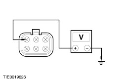
| | | Is the voltage greater than 10 volts? Yes No REPAIR circuit 29-AH35A (OG/YE) or circuit 29-AH42 (OG/YE). TEST the system for normal operation. | | A2: CHECK THE POWER SEAT CONTROL SWITCH GROUND CIRCUIT FOR CONTINUITY | | | 1 Ignition switch in position 0. | | | NOTE:Carry out the measurements on the inoperative seat. 2 Measure the resistance between the: - driver power seat control switch C60 pin 16, circuit 31-AH35 (BK) harness side and ground.
- passenger power seat control switch C61 pin 16, circuit 31-AH42 (BK) harness side and ground.
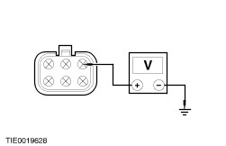
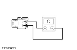
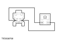
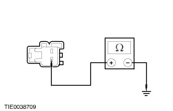
| | | Is the resistance less than 5 ohms? Yes Eight-way power seat - INSTALL a new power seat control switch. Two-Way power seat - INSTALL a new power seat control switch and motor. No REPAIR circuit 31-AH35 (BK) or circuit 31-AH42 (BK). TEST the system for normal operation. | | PINPOINT TEST B : THE POWER SEAT DOES NOT MOVE HORIZONTALLY | | TEST CONDITIONS | DETAILS/RESULTS/ACTIONS | | B1: CHECK THE VOLTAGE TO THE SEAT HORIZONTAL MOTOR | | | 1 Ignition switch in position 0. | | | 2 Detach the seat assembly from the floor. | | | 3 Disconnect Power Seat Horizontal Motor C467. | | | 4 Ignition switch in position II. | | | 5 Operate the power seat control switch to the REARWARD position. | | | 6 Measure the voltage between the power seat control switch C467 pin 1, circuit 33-AH9 (YE/GN), harness side and ground. | | | Is the voltage greater than 10 volts? Yes Yes REPAIR circuit 33-AH9 (YE/GN). TEST the system for normal operation. | | B2: CHECK THE FORWARD VOLTAGE TO THE SEAT HORIZONTAL MOTOR | | | 1 Operate the power seat control switch to the FORWARD position. | | | 2 Measure the voltage between the power seat control switch C467 pin 4, circuit 32-AH9 (WH/GN), harness side and ground. | | | Is the voltage greater than 10 volts? Yes INSTALL a new seat horizontal motor.
REFER to: Front Seat (501-10 Seating, Removal and Installation).
TEST the system for normal operation. No REPAIR circuit 32-AH9 (WH/GN). TEST the system for normal operation. | | PINPOINT TEST C : THE POWER SEAT DOES NOT MOVE VERTICALLY | NOTE:If the front seat front height motor is inoperative GO to C1, if the front seat rear height motor is inoperative GO to C3. | | TEST CONDITIONS | DETAILS/RESULTS/ACTIONS | | C1: CHECK THE VOLTAGE TO THE SEAT FRONT HEIGHT MOTOR | | | 1 Ignition switch in position 0. | | | 2 Detach the seat assembly from the floor. | | | 3 Disconnect Power Seat Front Height Motor C467. | | | 4 Ignition switch in position II. | | | 5 Operate the power seat control switch to the DOWN position. | | | 6 Measure the voltage between the power seat control switch C467 pin 3, circuit 33-AH10 (YE/BK), harness side and ground. | | | Is the voltage greater than 10 volts? Yes No REPAIR circuit 33-AH10 (YE/BK). TEST the system for normal operation. | | C2: CHECK THE VOLTAGE TO THE SEAT FRONT HEIGHT MOTOR (CONTINUED) | | | 1 Operate the power seat control switch to the UP position. | | | 2 Measure the voltage between the power seat control switch C467 pin 6, circuit 32-AH10 (WH/BK), harness side and ground. | | | Is the voltage greater than 10 volts? Yes INSTALL a new seat front height motor.
REFER to: Front Seat (501-10 Seating, Removal and Installation).
TEST the system for normal operation. No REPAIR circuit 32-AH10 (WH/BK). TEST the system for normal operation. | | C3: CHECK THE VOLTAGE TO THE SEAT REAR HEIGHT MOTOR | | | 1 Ignition switch in position 0. | | | 2 Detach the seat assembly from the floor. | | | 3 Disconnect Power Seat Rear Height Motor C467. | | | 4 Ignition switch in position II. | | | 5 Operate the power seat control switch to the DOWN position. | | | 6 Measure the voltage between the power seat control switch C467 pin 2, circuit 33-AH11 (YE/VT), harness side and ground. | | | Is the voltage greater than 10 volts? Yes No REPAIR circuit 33-AH11 (YE/VT). TEST the system for normal operation. | | C4: CHECK THE VOLTAGE TO THE SEAT REAR HEIGHT MOTOR (CONTINUED) | | | 1 Operate the power seat control switch to the UP position. | | | 2 Measure the voltage between the power seat control switch C467 pin 5, circuit 32-AH11 (WH/VT), harness side and ground. | | | Is the voltage greater than 10 volts? Yes INSTALL a new seat rear height motor.
REFER to: Front Seat (501-10 Seating, Removal and Installation).
TEST the system for normal operation. No REPAIR circuit 32-AH11 (WH/VT). TEST the system for normal operation. | | PINPOINT TEST D : THE POWER SEAT DOES NOT RECLINE | | TEST CONDITIONS | DETAILS/RESULTS/ACTIONS | | D1: CHECK THE VOLTAGE TO THE SEAT BACKREST MOTOR | | | 1 Ignition switch in position 0. | | | 2 Detach the seat assembly from the floor. | | | 3 Disconnect Power Seat Backrest Motor C463. | | | 4 Ignition switch in position II. | | | 5 Operate the power seat control switch to the REARWARD position. | | | 6 Measure the voltage between the power seat control switch C463 pin 1, circuit 33-AH7 (YE/RD), harness side and ground. | | | Is the voltage greater than 10 volts? Yes No REPAIR circuit 33-AH7 (YE/RD). TEST the system for normal operation. | | D2: CHECK THE VOLTAGE TO THE SEAT BACKREST MOTOR (CONTINUED) | | | 1 Operate the power seat control switch to the FORWARD position. | | | 2 Measure the voltage between the power seat control switch C463 pin 2, circuit 32-AH7 (WH/RD), harness side and ground. | | | Is the voltage greater than 10 volts? Yes INSTALL a new seat backrest motor.
REFER to: Front Seat Backrest - 1.8L Duratec-HE (MI4)/1.8L Duratec-SCi (MI4)/2.0L Duratec-HE (MI4)/2.5L Duratec-VE (VE6)/3.0L Duratec-SE (VE6)/2.0L Duratorq-Di/TDDi (Puma) Diesel/2.0L Duratorq-TDCi (Puma) Diesel/2.2L Duratorq-TDCi (Puma) Diesel (501-10 Seating, Disassembly and Assembly) /
Front Seat Backrest - Vehicles With: Climate Controlled Seats (501-10 Seating, Disassembly and Assembly) /
Front Seat Backrest - 3.0L Duratec-ST (VE6) (501-10 Seating, Disassembly and Assembly).
TEST the system for normal operation. No REPAIR circuit 32-AH7 (WH/RD). TEST the system for normal operation. | | PINPOINT TEST E : THE HEATED SEATS ARE INOPERATIVE – FRONT SEATS | | TEST CONDITIONS | DETAILS/RESULTS/ACTIONS | | E1: CHECK FOR VOLTAGE TO THE HEATED SEAT CONTROL SWITCH | | | 1 Ignition switch in position II. | | | 2 Operate the heated seat control switch. | | | Does the heated seat control switch LEDs illuminate? Yes No | | E2: CHECK FOR VOLTAGE TO THE INOPERATIVE HEATED SEAT | | | 1 Ignition switch in position 0. | | | 2 Disconnect Left-hand Heated Seat C60 or C61. | | | 3 Ignition switch in position II. | | | 4 Measure the voltage between the: Left-hand drive - driver heated seat C60 pin 9, circuit 15-HC21A (GN/BK), harness side and ground.
Right-hand drive - passenger heated seat C61 pin 9, circuit 15-HC21A (GN/BK), harness side and ground.
| | | Is the voltage greater than 10 volts? Yes No | | E3: CHECK FOR CONTINUITY BETWEEN THE HEATED SEAT CONTROL SWITCH AND THE HEATED SEAT | | | 1 Ignition switch in position 0. | | | 2 Disconnect Heated Seat Control Switch C471. | | | 3 Measure the resistance between the left-hand heated seat C60 (LHD [C61 RHD]) pin 17, circuit 8-HC21 (WH/GN), harness side and the heated seat control switch C471 pin 2, circuit 8-HC21A (WH/GN), harness side. | | | Is the resistance less than 5 ohms? Yes VERIFY the customer concern. No REPAIR circuit 8-HC21A (WH/GN). TEST the system for normal operation. | | E4: CHECK THE HEATED SEAT CONTROL SWITCH GROUND CIRCUIT | | | 1 Ignition switch in position 0. | | | 2 Measure the resistance between the heated seat control switch C471 pin 1, circuit 31-LH29 (BK), harness side and ground. | | | Is the resistance less than 5 ohms? Yes No REPAIR circuit 31S-LH29 (BK). TEST the system for normal operation. | | E5: CHECK FOR VOLTAGE TO THE HEATED SEAT CONTROL SWITCH | | | 1 Ignition switch in position II. | | | 2 Measure the voltage between the: - heated seat control switch control switch C471 pin 4, circuit 15-HC14 (GN/YE), harness side and ground.
- heated seat control switch control switch C471 pin 6, circuit 29-HC14 (OG/YE), harness side and ground.
| | | Are the voltages greater than 10 volts? Yes INSTALL a new heated seat control switch.
REFER to: Climate Controlled Seat Switch (501-10 Seating, Removal and Installation).
TEST the system for normal operation. No REPAIR circuit 15-HC14 (GN/YE) or circuit 29-HC14 (OG/YE). TEST the system for normal operation. | | E6: CHECK THE IGNITION RELAY 2 GROUND CIRCUIT | | | 1 Ignition switch in position 0. | | | 2 Disconnect Ignition Relay 2 C200. | | | 3 Measure the resistance between the ignition relay 2 C200 pin 1, circuit 31-BB7A (BK), harness side and ground. | | | Is the resistance less than 5 ohms? Yes No REPAIR circuit 31-BB7A (BK). TEST the system for normal operation. | | E7: CHECK FOR IGNITION VOLTAGE TO THE HEATED SEAT CONTROL SWITCH | | | 1 Ignition switch in position II. | | | 2 Measure the voltage between the ignition relay 2 C200 pin 2, circuit 15-DA2B (GN/BU), harness side and ground. | | | Is the voltage greater than 10 volts? Yes No REPAIR circuit 15-DA2B (GN/BU). TEST the system for normal operation. | | E8: CHECK FOR BATTERY VOLTAGE TO THE HEATED SEAT CONTROL SWITCH | | | 1 Ignition switch in position 0. | | | 2 Measure the voltage between the ignition relay 2 C200 pin 3, circuit 30-HC21 (RD), harness side and ground. | | | Is the voltage greater than 10 volts? Yes No REPAIR circuit circuit 30-HC21 (RD). TEST the system for normal operation. | | E9: CHECK FOR CONTINUITY BETWEEN THE IGNITION RELAY 2 AND THE HEATED SEAT MODULE | | | 1 Measure the resistance between the ignition relay 2 C200 pin 5, circuit 15-HC21 (GN/BK), harness side and the heated seat C60 pin 9, circuit 15-HC21A (GN/BK), harness side and ground. | | | Is the resistance less than 5 ohms? Yes INSTALL a new ignition relay 2. TEST the system for normal operation. No REPAIR circuit 15-HC21 (GN/BK). TEST the system for normal operation. | | PINPOINT TEST F : THE HEATED SEATS ARE INOPERATIVE – REAR SEATS | | TEST CONDITIONS | DETAILS/RESULTS/ACTIONS | | F1: CHECK FOR VOLTAGE TO THE HEATED SEAT CONTROL SWITCH | | | 1 Ignition switch in position II. | | | 2 Operate the heated seat control switch. | | | Do the heated seat control switch LEDs illuminate? Yes No | | F2: CHECK FOR VOLTAGE TO THE INOPERATIVE HEATED SEAT | | | 1 Ignition switch in position 0. | | | 2 Disconnect Heated Seat C58. | | | 3 Ignition switch in position II. | | | 4 Operate the heated seat control switch. | | | 5 Measure the voltage between the left-hand heated seat module C58 pin 1, circuit 15-HC25A (GN/RD), harness side and ground. | | | Is the voltage greater than 10 volts? Yes No REPAIR circuit 15-HC25 (GN/RD). TEST the system for normal operation. | | F3: CHECK FOR CONTINUITY BETWEEN THE HEATED SEAT CONTROL SWITCH AND THE INOPERATIVE HEATED SEAT | | | 1 Ignition switch in position 0. | | | 2 Disconnect Heated Seat Control Switch C472. | | | 3 Measure the resistance between the heated seat control switch C472 pin 2, circuit 8-HC25 (WH/BU), harness side and the heated seat C58 pin 3, circuit 8-HC25A (WH/BU), harness side. | | | Is the resistance less than 5 ohms? Yes VERIFY the customer concern. No REPAIR circuit 8-HC25 (WH/BU). TEST the system for normal operation. | | F4: CHECK FOR CONTINUITY BETWEEN THE HEATED SEAT CONTROL SWITCH AND GROUND | | | 1 Ignition switch in position 0. | | | 2 Disconnect Heated Seat Control Switch C472. | | | 3 Measure the resistance between the heated seat control switch C472 pin 1, circuit 31-HC26 (BK), harness side and ground. | | | Is the resistance less than 5 ohms? Yes No REPAIR circuit 31-HC26 (BK). TEST the system for normal operation. | | F5: CHECK FOR VOLTAGE TO THE HEATED SEAT CONTROL SWITCH | | | 1 Ignition switch in position II. | | | 2 Measure the voltage between the: - heated seat control switch control switch C472 pin 4, circuit 15-HC26 (GN/OG), harness side and ground.
- heated seat control switch control switch C471 pin 6, circuit C472 pin 6, circuit 15-HC26A (GN/OG), harness side and ground.
| | | Are the voltages greater than 10 volts? Yes No REPAIR circuit 15-HC26 (GN/OG) or circuit 15-HC26A (GN/OG). TEST the system for normal operation. | | F6: CHECK FOR CONTINUITY BETWEEN THE HEATED SEAT CONTROL SWITCH AND THE HEATED SEAT | | | 1 Ignition switch in position 0. | | | 2 Measure the resistance between the left-hand heated seat C58 pin 3, circuit 8-HC25A (WH/BU), harness side and the heated seat control switch C472 pin 2, circuit 8-HC25 (WH/BU), harness side. | | | Is the resistance less than 5 ohms? Yes VERIFY the customer concern. No REPAIR circuit 8-HC25 (WH/BU). TEST the system for normal operation. | | PINPOINT TEST G : THE HEATED SEAT IS INOPERATIVE – FRONT SEAT | | TEST CONDITIONS | DETAILS/RESULTS/ACTIONS | | G1: CHECK THE INOPERATIVE HEATED SEAT GROUND CIRCUIT | | | 1 Disconnect Inoperative Heated Seat C60 or C61. | | | 2 Measure the resistance between the: Left-hand drive - driver heated seat C60 pin 10, circuit 31-HC21 (BK), harness side and ground.
- driver heated seat C60 pin 18, circuit 31-HC21C (BK), harness side and ground.
- passenger heated seat C61 pin 10, circuit 31-HC22 (BK) harness side and ground.
Right-hand drive - driver heated seat C60 pin 10, circuit 31-HC22 (BK), harness side and ground.
- passenger heated seat C61 pin 10, circuit 31-HC21 (BK) harness side and ground.
- passenger heated seat C61 pin 18, circuit 31-HC21C (BK) harness side and ground.
| | | Is the resistance(s) less than 5 ohms? Yes No REPAIR circuit 31-HC21 (BK), or circuit 31-HC21C (BK) or circuit 31-HC22 (BK). TEST the system for normal operation. | | G2: CHECK FOR VOLTAGE TO THE INOPERATIVE HEATED SEAT | | | 1 Ignition switch in position II. | | | 2 Measure the voltage between the: Left-hand rive - driver heated seat C60 pin 9, circuit 15-HC21A (GN/BK), harness side and ground.
- passenger heated seat C61 pin 9, circuit 15-HC22 (GN/YE), harness side and ground.
Right-hand drive - driver heated seat C60 pin 9, circuit 15-HC22 (GN/YE), harness side and ground.
- passenger heated seat C61 pin 9, circuit 15-HC21A (GN/BK), harness side and ground.
| | | Is the voltage greater than 10 volts? Yes No REPAIR circuit 15-HC21A (GN/BK) or circuit 15S-HC22 (GN/YE). TEST the system for normal operation. | | G3: CHECK CONTINUITY BETWEEN THE HEATED SEAT CONTROL SWITCH AND HEATED SEAT | | | 1 Ignition switch in position 0. | | | 2 Disconnect Heated Seat Control Switch C471. | | | 3 Measure the resistance between the: Left-hand drive - driver heated seat C60 pin 17, circuit 8-HC21 (WH/GN), harness side and the heated seat control switch C471 pin 2, circuit 8-HC21A (WH/GN), harness side.
- passenger heated seat C61 pin 17, circuit 8-HC22 (WH), harness side and the heated seat control switch C471 pin 2, circuit 8-HC21A (WH/GN), harness side.
Right-hand drive - driver heated seat C60 pin 17, circuit 8-HC22 (WH), harness side and the heated seat control switch C471 pin 2, circuit 8-HC21A (WH/GN), harness side.
- passenger heated seat C61 pin 17, circuit 8-HC21 (WH/GN), harness side and the heated seat control switch C471 pin 2, circuit 8-HC21A (WH/GN), harness side.
| | | Is the resistance less than 5 ohms? Yes No REPAIR circuit 8-HC21 (WH/GN) or 8-HC22 (WH). TEST the system for normal operation. | | G4: CHECK THE INOPERATIVE HEATED SEAT MODULE GROUND CIRCUIT | | | 1 Disconnect Inoperative Heated Seat Module. | | | 2 Connect Inoperative Heated Seat C60 or C61. | | | 3 Measure the resistance between the: Left-hand seat - heated seat module pin 4, circuit 31-HC21 (BK), harness side and ground.
- heated seat module pin 2, circuit 31-HC21C (BK/YE), harness side and ground.
Right-hand seat - heated seat module pin 4, circuit 31-HC22 (BK), harness side and ground.
| | | Are the resistances less than 5 ohms? Yes No INSTALL a new seat wiring sub-harness. TEST the system for normal operation. | | G5: CHECK FOR CONTINUITY BETWEEN THE HEATED SEAT CONTROL SWITCH AND THE INOPERATIVE HEATED SEAT MODULE | | | 1 Measure the resistance between the: Left-hand drive - driver heated seat module pin 3, circuit 8-HC21 (WH), harness side and the heated seat control switch C471 pin 2, circuit 8-HC21A (WH/GN), harness side.
- passenger heated seat module pin 3, circuit 8-HC22 (WH), harness side and the heated seat control switch C471 pin 2, circuit 8-HC21A (WH/GN), harness side.
Right-hand drive - driver heated seat module pin 3, circuit 8-HC22 (WH), harness side and the heated seat control switch C471 pin 2, circuit 8-HC21A (WH/GN), harness side.
- passenger heated seat module pin 3, circuit 8-HC21 (WH), harness side and the heated seat control switch C471 pin 2, circuit 8-HC21A (WH/GN), harness side.
| | | Is the resistance less than 5 ohms? Yes No INSTALL a new seat wiring sub-harness. TEST the system for normal operation. | | G6: CHECK FOR VOLTAGE TO THE INOPERATIVE HEATED SEAT MODULE | | | 1 Ignition switch in position II. | | | 2 Measure the voltage between the: Left-hand drive - driver heated seat module pin 1, circuit 15-HC21A (GN), harness side and ground.
- passenger heated seat module pin 1, circuit 15-HC22 (GN), harness side and ground.
Right-hand drive - driver heated seat module pin 1, circuit 15-HC22 (GN), harness side and ground.
- passenger heated seat module pin 1, circuit 15-HC21A (GN), harness side and ground.
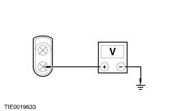
| | | Is the voltage greater than 10 volts? Yes No INSTALL a new seat wiring sub-harness. TEST the system for normal operation. | | G7: CHECK THE INOPERATIVE HEATED SEAT BACKREST HEATER MAT FOR CONTINUITY | | | 1 Ignition switch in position 0. | | | 2 Disconnect Inoperative Heated Seat Backrest. | | | 3 Measure the resistance between the: - driver heated seat backrest pin 1 and pin 2, component side.
- passenger heated seat backrest pin 1 and pin 2, component side.
| | | Is the resistance less than 5 ohms? Yes INSTALL a new heated seat module and cushion heater mat.
REFER to: Front Seat Cushion - 1.8L Duratec-HE (MI4)/1.8L Duratec-SCi (MI4)/2.0L Duratec-HE (MI4)/2.5L Duratec-VE (VE6)/3.0L Duratec-SE (VE6)/2.0L Duratorq-Di/TDDi (Puma) Diesel/2.0L Duratorq-TDCi (Puma) Diesel/2.2L Duratorq-TDCi (Puma) Diesel (501-10 Seating, Disassembly and Assembly) /
Front Seat Cushion - 3.0L Duratec-ST (VE6) (501-10 Seating, Disassembly and Assembly) /
Front Seat Cushion - Vehicles With: Climate Controlled Seats (501-10 Seating, Disassembly and Assembly).
TEST the system for normal operation. No INSTALL a new heated seat backrest heater mat.
REFER to: Front Seat Backrest - 1.8L Duratec-HE (MI4)/1.8L Duratec-SCi (MI4)/2.0L Duratec-HE (MI4)/2.5L Duratec-VE (VE6)/3.0L Duratec-SE (VE6)/2.0L Duratorq-Di/TDDi (Puma) Diesel/2.0L Duratorq-TDCi (Puma) Diesel/2.2L Duratorq-TDCi (Puma) Diesel (501-10 Seating, Disassembly and Assembly) /
Front Seat Backrest - 3.0L Duratec-ST (VE6) (501-10 Seating, Disassembly and Assembly) /
Front Seat Backrest - Vehicles With: Climate Controlled Seats (501-10 Seating, Disassembly and Assembly).
TEST the system for normal operation. | | PINPOINT TEST H : THE HEATED SEAT IS INOPERATIVE – REAR SEAT | | TEST CONDITIONS | DETAILS/RESULTS/ACTIONS | | H1: CHECK THE INOPERATIVE HEATED SEAT GROUND CIRCUIT | | | 1 Disconnect Inoperative Heated Rear Seat C58 or C59. | | | 2 Measure the resistance between the: - left-hand heated rear seat module C58 pin 4, circuit 31-HC25A (BK), harness side and ground.
- right-hand heated rear seat module C59 pin 4, circuit 31-HC25B (BK), harness side and ground.
| | | Is the resistance less than 5 ohms? Yes No REPAIR circuit 31-HC25A (BK) or circuit 31-HC25B (BK). TEST the system for normal operation. | | H2: CHECK FOR VOLTAGE TO THE INOPERATIVE HEATED SEAT | | | 1 Ignition switch in position II. | | | 2 Measure the voltage between the: - left-hand heated seat module C58 pin 1, circuit 15-HC25A (GN/RD), harness side and ground.
- right-hand heated seat module C59 pin 1, circuit 15-HC25B (GN/RD), harness side and ground.
| | | Is the voltage greater than 10 volts? Yes No REPAIR circuit 15-HC25A (GN/RD), left-hand heated rear seat or circuit 15-HC25B (GN/RD), right-hand heated rear seat. TEST the system for normal operation. | | H3: CHECK FOR CONTINUITY BETWEEN THE HEATED SEAT CONTROL SWITCH AND THE INOPERATIVE HEATED SEAT | | | 1 Ignition switch in position 0. | | | 2 Disconnect Heated Seat Control Switch C472. | | | 3 Measure the resistance between the: - heated seat control switch C472 pin 2, circuit 8-HC25 (WH/BU), harness side and the left-hand heated seat C58 pin 3, circuit 8-HC25A (WH/BU), harness side.
- heated seat control switch C472 pin 2, circuit 8-HC25 (WH/BU), harness side and the right-hand heated seat C59 pin 3, circuit 8-HC25B (WH/BU), harness side.
| | | Is the resistance less than 5 ohms? Yes No REPAIR circuit 8-HC25A (WH/BU) or circuit 8-HC25B (WH/BU). TEST the system for normal operation. | | H4: CHECK THE INOPERATIVE HEATED SEAT BACKREST FOR CONTINUITY | | | 1 Disconnect Inoperative Heated Seat Backrest. | | | 2 Measure the resistance between the: - left-hand heated seat backrest C65 pin 1, circuit 15-HC27 (GN/RD), component side and pin 2, circuit 31-HC27 (BK), component side.
- right-hand heated seat backrest C66 pin 1, circuit 15-HC28 (GN/BK), component side and pin 2, circuit 31-HC28 (BK), component side.
| | | Is the resistance less than 5 ohms? Yes INSTALL a new heated seat module and cushion heater mat.
REFER to: Front Seat Cushion - 1.8L Duratec-HE (MI4)/1.8L Duratec-SCi (MI4)/2.0L Duratec-HE (MI4)/2.5L Duratec-VE (VE6)/3.0L Duratec-SE (VE6)/2.0L Duratorq-Di/TDDi (Puma) Diesel/2.0L Duratorq-TDCi (Puma) Diesel/2.2L Duratorq-TDCi (Puma) Diesel (501-10 Seating, Disassembly and Assembly) /
Front Seat Cushion - 3.0L Duratec-ST (VE6) (501-10 Seating, Disassembly and Assembly) /
Front Seat Cushion - Vehicles With: Climate Controlled Seats (501-10 Seating, Disassembly and Assembly).
TEST the system for normal operation. No INSTALL a new heated seat backrest heater mat.
REFER to: Front Seat Backrest - 1.8L Duratec-HE (MI4)/1.8L Duratec-SCi (MI4)/2.0L Duratec-HE (MI4)/2.5L Duratec-VE (VE6)/3.0L Duratec-SE (VE6)/2.0L Duratorq-Di/TDDi (Puma) Diesel/2.0L Duratorq-TDCi (Puma) Diesel/2.2L Duratorq-TDCi (Puma) Diesel (501-10 Seating, Disassembly and Assembly) /
Front Seat Backrest - 3.0L Duratec-ST (VE6) (501-10 Seating, Disassembly and Assembly) /
Front Seat Backrest - Vehicles With: Climate Controlled Seats (501-10 Seating, Disassembly and Assembly).
TEST the system for normal operation. | | PINPOINT TEST I : ALL CLIMATE CONTROLLED SEATS ARE INOPERATIVE/DO NOT OPERATE CORRECTLY | | TEST CONDITIONS | DETAILS/RESULTS/ACTIONS | | I1: CHECK FOR VOLTAGE TO THE CLIMATE CONTROLLED SEAT CONTROL SWITCH | | | 1 Ignition switch in position II. | | | 2 Operate the climate controlled seat control switch. | | | Do the climate controlled seat control switch LEDs illuminate? Yes No | | I2: CHECK FOR VOLTAGE TO THE INOPERATIVE CLIMATE CONTROLLED SEAT | | | 1 Ignition switch in position 0. | | | 2 Disconnect Inoperative Climate Controlled Seat C60 or C61. | | | 3 Ignition switch in position II. | | | 4 Operate the climate controlled seat control switch. | | | 5 Measure the voltage between the: Left-hand drive - driver climate controlled seat C60 pin 9, circuit 15-HC21A (GN/BK) harness side and ground.
- passenger climate controlled seat C61 pin 9, circuit 15-HC22 (GN/YE) harness side and ground.
Right-hand drive - driver climate controlled seat C60 pin 9, circuit 15-HC22 (GN/YE) harness side and ground.
- passenger climate controlled seat C61 pin 9, circuit 15-HC21A (GN/BK) harness side and ground.
| | | Is the voltage greater than 10 volts? Yes No | | I3: CHECK FOR CONTINUITY BETWEEN THE CLIMATE CONTROLLED SEAT CONTROL SWITCH AND THE CLIMATE CONTROLLED SEAT | | | 1 Ignition switch in position 0. | | | 2 Disconnect Climate Controlled Seat Control Switch C471. | | | 3 Measure the resistance between the driver climate controlled seat C60 pin 17, circuit 8-HC21 (WH/GN), harness side and the climate controlled seat control switch C471 pin 2, circuit 8-HC21A (WH/GN), harness side. | | | Is the resistance less than 5 ohms? Yes VERIFY the customer concern. No REPAIR circuit 8-HC21A (WH/GN). TEST the system for normal operation. | | I4: CHECK THE CLIMATE CONTROLLED SEAT CONTROL SWITCH GROUND CIRCUIT | | | 1 Ignition switch in position 0. | | | 2 Measure the resistance between the climate controlled seat control switch control switch C471 pin 1, circuit 31-LH29 (BK), harness side and ground. | | | Is the resistance less than 5 ohms? Yes No REPAIR circuit 31-LH29 (BK). TEST the system for normal operation. | | I5: CHECK FOR VOLTAGE TO THE CLIMATE CONTROLLED SEAT CONTROL SWITCH | | | 1 Ignition switch in position II. | | | 2 Measure the voltage between the: - climate controlled seat control switch control switch C471 pin 4, circuit 15-HC14 (GN/YE), harness side and ground.
- climate controlled seat control switch control switch C471 pin 6, circuit 29-HC14 (OG/YE), harness side and ground.
| | | Is the voltage greater than 10 volts? Yes INSTALL a new climate controlled seat control switch.
REFER to: Climate Controlled Seat Switch (501-10 Seating, Removal and Installation).
TEST the system for normal operation. No REPAIR circuit 15-HC14 (GN/YE) or circuit 29-HC14 (OG/YE). TEST the system for normal operation. | | I6: CHECK THE IGNITION RELAY 2 GROUND CIRCUIT | | | 1 Ignition switch in position 0. | | | 2 Disconnect Ignition Relay 2 C200. | | | 3 Measure the resistance between ignition relay 2 C200 pin 1, circuit 31-BB7A (BK), harness side and ground. | | | Is the resistance less than 5 ohms? Yes No REPAIR circuit 31-BB7A (BK). TEST the system for normal operation. | | I7: CHECK FOR BATTERY VOLTAGE TO THE CLIMATE CONTROLLED SEAT CONTROL SWITCH | | | 1 Measure the voltage between the ignition relay 2 C200 pin 3, circuit 30-HC21 (RD), harness side and ground. | | | Is the voltage greater than 10 volts? Yes No REPAIR circuit 30-HC21 (RD). TEST the system for normal operation. | | I8: CHECK FOR IGNITION VOLTAGE TO THE CLIMATE CONTROLLED SEAT CONTROL SWITCH | | | 1 Ignition switch in position II. | | | 2 Measure the voltage between the ignition relay 2 C200 pin 2, circuit 15-DA2B (GN/BU), harness side and ground. | | | Is the voltage greater than 10 volts? Yes No REPAIR circuit 15-DA2B (GN/BU). TEST the system for normal operation. | | I9: CHECK FOR CONTINUITY BETWEEN THE IGNITION RELAY AND CLIMATE CONTROLLED SEAT | | | 1 Ignition switch in position 0. | | | 2 Measure the resistance between ignition relay 2 C200 pin 5, circuit 15-HC21 (GN/BK), harness side and the climate controlled seat C60 pin 9, circuit 15-HC21A (GN/BK), harness side and ground. | | | Is the resistance less than 5 ohms? Yes INSTALL a new ignition relay 2. TEST the system for normal operation. No REPAIR circuit 15-HC21 (GN/BK). TEST the system for normal operation. | | PINPOINT TEST J : A SINGLE CLIMATE CONTROLLED SEAT IS INOPERATIVE/DOES NOT OPERATE CORRECTLY | | TEST CONDITIONS | DETAILS/RESULTS/ACTIONS | | J1: CHECK THE CLIMATE CONTROLLED SEAT HEATER OPERATION | | | 1 Ignition switch in position II. | | | 2 Operate the climate controlled seat control switch. | | | Does the climate controlled seat heater mats operate correctly? Yes No | | J2: CHECK THE CLIMATE CONTROLLED SEAT FAN OPERATION | | | 1 Operate the climate controlled seat control switch. | | | Does the climate seat fans operate correctly? Yes VERIFY the customer concern. No | | J3: CHECK FOR VOLTAGE TO THE INOPERATIVE CLIMATE CONTROLLED SEAT | | | 1 Ignition switch in position 0. | | | 2 Disconnect Inoperative Underseat Electrical Connector C60 or C61. | | | 3 Ignition switch in position II. | | | 4 Operate the climate controlled seat control switch. | | | 5 Measure the voltage between the: Left-hand drive - driver underseat connector C60 pin 9, circuit 15-HC21A (GN/BK), harness side and ground.
- passenger underseat connector C61 pin 9, circuit 15-HC22 (GN/YE), harness side and ground.
Right-hand drive - driver underseat connector C60 pin 9, circuit 15-HC22 (GN/YE), harness side and ground.
- passenger underseat connector C61 pin 9, circuit 15-HC21A (GN/BK), harness side and ground.
| | | Is the voltage greater than 10 volts? Yes No REPAIR circuit 15-HC21A (GN/BK) or circuit 15-HC22 (GN/YE). TEST the system for normal operation. | | J4: CHECK FOR VOLTAGE TO THE INOPERATIVE CLIMATE CONTROLLED SEAT HEATER MODULE | | | 1 Ignition switch in position 0. | | | 2 Connect Inoperative Seat Underseat Electrical Connector C60 or C61. | | | 3 Disconnect Inoperative Seat Heater Module. | | | 4 Ignition switch in position II. | | | 5 Operate the climate controlled seat control switch. | | | 6 Measure the voltage between the: - driver seat heater module electrical connector pin 1, (GN), harness side and ground.
- passenger seat heater module electrical connector pin 1, (GN), harness side and ground.
| | | Is the voltage greater than 10 volts? Yes No INSTALL a new climate controlled seat wiring harness. TEST the system for normal operation. | | J5: CHECK FOR VOLTAGE TO THE INOPERATIVE CLIMATE CONTROLLED SEAT CONTROL MODULE | | | 1 Ignition switch in position 0. | | | 2 Disconnect Inoperative Seat Climate Controlled Seat Control Module. | | | 3 Ignition switch in position II. | | | 4 Operate the climate controlled seat control switch. | | | 5 Measure the voltage between the: - driver climate controlled seat control module pin 9, (GN), harness side and ground.
- passenger climate controlled seat control module pin 9, (GN), harness side and ground.
| | | Is the voltage greater than 10 volts? Yes No INSTALL a new climate controlled seat wiring harness. TEST the system for normal operation. | | J6: CHECK FOR VOLTAGE TO THE INOPERATIVE CLIMATE CONTROLLED SEAT BACKREST HEATER MAT | | | 1 Ignition switch in position 0. | | | 2 Connect Inoperative Seat Climate Seat Control Module. | | | 3 Disconnect Inoperative Front Seat Backrest Heater Mat. | | | 4 Ignition switch in position II. | | | 5 Operate the climate controlled seat control switch. | | | 6 Measure the voltage between the: - driver front seat backrest heater mat connector pin 1, (RD/BK), harness side and ground.
- passenger front seat backrest heater mat connector pin 1, circuit 15S-HC9 (RD/BK) harness side and ground.
| | | Is the voltage greater than 10 volts? Yes No INSTALL a new heated seat module and cushion heater mat.
REFER to: Front Seat Cushion - Vehicles With: Climate Controlled Seats (501-10 Seating, Disassembly and Assembly).
TEST the system for normal operation. | | J7: CHECK THE INOPERATIVE CLIMATE CONTROLLED SEAT HEATED SEAT BACKREST HEATER MAT FOR CONTINUITY | | | 1 Ignition switch in position 0. | | | 2 Measure the resistance between the front seat backrest pin 1 (RD/BK) and pin 2 (BK), component side. | | | Is the resistance less than 5 ohms? Yes INSTALL a new heated seat module and cushion heater mat.
REFER to: Front Seat Cushion - 1.8L Duratec-HE (MI4)/1.8L Duratec-SCi (MI4)/2.0L Duratec-HE (MI4)/2.5L Duratec-VE (VE6)/3.0L Duratec-SE (VE6)/2.0L Duratorq-Di/TDDi (Puma) Diesel/2.0L Duratorq-TDCi (Puma) Diesel/2.2L Duratorq-TDCi (Puma) Diesel (501-10 Seating, Disassembly and Assembly) /
Front Seat Cushion - 3.0L Duratec-ST (VE6) (501-10 Seating, Disassembly and Assembly) /
Front Seat Cushion - Vehicles With: Climate Controlled Seats (501-10 Seating, Disassembly and Assembly).
TEST the system for normal operation. No INSTALL a new front seat backrest heater mat.
REFER to: Front Seat Backrest - Vehicles With: Climate Controlled Seats (501-10 Seating, Disassembly and Assembly).
TEST the system for normal operation. | | J8: CHECK THE CLIMATE CONTROLLED SEAT FAN OPERATION | | | 1 Operate the climate controlled seat control switch. | | | Does the climate controlled front seat backrest fans operate correctly? Yes No | | J9: CHECK THE INOPERATIVE CLIMATE CONTROLLED SEAT FRONT SEAT CUSHION FAN GROUND CIRCUIT | | | 1 Ignition switch in position 0. | | | 2 Disconnect Inoperative Front Seat Cushion Fans. | | | 3 Measure the resistance between the front seat cushion fan pin 2, (BK), harness side and ground. | | | Is the resistance less than 5 ohms? Yes No INSTALL a new climate controlled seat wiring harness. TEST the system for normal operation. | | J10: CHECK FOR VOLTAGE TO THE INOPERATIVE CLIMATE CONTROLLED SEAT FRONT SEAT CUSHION FANS | | | 1 Ignition switch in position II. | | | 2 Operate the climate controlled seat control switch. | | | 3 Measure the voltage between the front seat cushion fan pin 1, (RD), harness side and ground. | | | Is the voltage greater than 6 volts? Yes INSTALL new climate controlled front seat cushion fans. TEST the system for normal operation. No | | J11: CHECK FOR VOLTAGE TO THE INOPERATIVE CLIMATE CONTROLLED SEAT HEATER MODULE | | | 1 Ignition switch in position 0. | | | 2 Disconnect Inoperative Front Seat Backrest Fans. | | | 3 Measure the resistance between the front seat backrest fan pin 2, (BK), harness side and ground. | | | Is the resistance less than 5 ohms? Yes No INSTALL a new climate controlled seat wiring harness. TEST the system for normal operation. | | J12: CHECK FOR VOLTAGE TO THE INOPERATIVE CLIMATE CONTROLLED SEAT FRONT SEAT BACKREST FANS | | | 1 Ignition switch in position II. | | | 2 Operate the climate controlled seat control switch. | | | 3 Measure the voltage between the front seat backrest fans pin 1, (RD/BK), harness side and ground. | | | Is the voltage greater than 6 volts? Yes INSTALL new climate controlled front seat backrest fans.
REFER to: Front Seat Backrest - Vehicles With: Climate Controlled Seats (501-10 Seating, Disassembly and Assembly).
TEST the system for normal operation. No | | J13: CHECK FOR CONTINUITY BETWEEN THE INOPERATIVE CLIMATE CONTROLLED SEAT CUSHION FANS AND THE CLIMATE CONTROLLED SEAT MODULE | | | 1 Ignition switch in position 0. | | | 2 Disconnect Inoperative Front Seat Climate Controlled Seat Control Module. | | | 3 Measure the resistance between the climate controlled seat control module pin 6, (RD), harness side and the front seat cushion fans pin 1, (RD), harness side. | | | Is the resistance less than 5 ohms? Yes INSTALL a new climate controlled seat control module.
REFER to: Front Seat Cushion - Vehicles With: Climate Controlled Seats (501-10 Seating, Disassembly and Assembly).
TEST the system for normal operation. No INSTALL a new climate controlled seat wiring harness. TEST the system for normal operation. | | J14: CHECK FOR CONTINUITY BETWEEN THE INOPERATIVE CLIMATE CONTROLLED SEAT BACKREST FANS AND THE CLIMATE CONTROLLED SEAT MODULE | | | 1 Ignition switch in position 0. | | | 2 Disconnect Inoperative Front Seat Climate Controlled Seat Control Module. | | | 3 Measure the resistance between the climate controlled seat control module pin 1, (BK/RD), harness side and the front seat backrest fans pin 1, (RD/BK), harness side. | | | Is the resistance less than 5 ohms? Yes INSTALL a new climate controlled seat control module.
REFER to: Front Seat Cushion - Vehicles With: Climate Controlled Seats (501-10 Seating, Disassembly and Assembly).
TEST the system for normal operation. No INSTALL a new climate controlled seat wiring harness. TEST the system for normal operation. | | PINPOINT TEST K : THE TEMPERATURE IS NOT EQUAL BETWEEN THE SEAT CUSHION AND THE BACKREST – REAR SEAT | | TEST CONDITIONS | DETAILS/RESULTS/ACTIONS | | K1: CHECK FOR VOLTAGE TO THE REAR SEAT BACKREST HEATER MAT | | | 1 Ignition switch in position 0. | | | 2 Disconnect Inoperative Rear Seat Backrest Heater Mat C65 or C66. | | | 3 Ignition switch in position II. | | | 4 Operate the heated seat control switch. | | | 5 Measure the voltage between the: - left-hand rear heated seat backrest heater mat C65 pin 1, circuit 15-HC27 (GN/RD), harness side and ground.
- right-hand rear heated seat backrest heater mat C66 pin 1, circuit 15-HC28 (GN/BK), harness side and ground.
| | | Is the voltage greater than 10 volts? Yes No REPAIR circuit 15-HC27 (GN/RD) or circuit 15-HC28 (GN/BK). TEST the system for normal operation. | | K2: CHECK FOR CONTINUITY BETWEEN THE HEATED REAR SEAT MODULE AND THE REAR SEAT BACKREST HEATER MAT | | | 1 Ignition switch in position 0. | | | 2 Disconnect Inoperative Heated Rear Seat Module C58 or C59. | | | 3 Measure the resistance between the: - left-hand heated rear seat module C58 pin 6, circuit 31-HC27 (BK), harness side and the left-hand rear heated seat backrest heater mat C65 pin 2, circuit 31-HC27 (BK), harness side.
- right-hand heated rear seat module C59 pin 6, circuit 31-HC28 (BK), harness side and the right-hand rear heated seat backrest heater mat C66 pin 2, circuit 31-HC28 (BK), harness side.
| | | Is the resistance less than 5 ohms? Yes No REPAIR circuit 31-HC27 (BKE) or circuit 31-HC28 (BK). TEST the system for normal operation. | | K3: CHECK FOR SHORT CIRCUIT BETWEEN THE HEATED REAR SEAT MODULE AND THE REAR SEAT BACKREST HEATER MAT | | | 1 Measure the resistance between the: - left-hand rear heated seat backrest heater mat C65 pin 1, circuit 15-HC27 (GN/RD) and pin 2, circuit 31-HC27 (BK), harness side.
- right-hand rear heated seat backrest heater mat C66 pin 1, circuit 15-HC28 (GNBK) harness side and pin 2, circuit 31-HC28 (BK), harness side.
| | | Is the resistance greater than 10,000 ohms? Yes INSTALL a new heated seat backrest heater mat.
REFER to: Rear Seat Backrest (501-10 Seating, Disassembly and Assembly).
TEST the system for normal operation. No REPAIR circuits 15-HC27 (GN/RD) and 31-HC27 (BK); or circuits 15-HC28 (GNBK) and 31-HC28 (BK). TEST the system for normal operation. | |