| Diagnosis and Testing Refer to Wiring Diagrams Section 417-01, for schematic and connector information. Special Tool(s) | | Terminal Probe Kit 29-011A | General Equipment Digital Multimeter. Diagnostic tool. Inspection and Verification NOTE:The generic electronic module (GEM) is part of the central junction box (CJB). NOTE:If a new GEM module is being installed, the new module must be configured following installation. For this purpose, the vehicle-specific data is read out of the module to be changed using the diagnostic unit and is transferred to the new module. REFER to: Module Configuration (418-01 Module Configuration, General Procedures), Generic Electronic Module (GEM) (419-10 Multifunction Electronic Modules, Diagnosis and Testing). NOTE:Before reading out the vehicle-specific data make sure that all electrical connections in the vehicle are reconnected so that the module and the diagnostic unit can communicate correctly. NOTE:Ensure correct engagement of the wiring harness connectors. - Verify the customer concern.
- Visually inspect for obvious signs of mechanical or electrical damage.
Visual inspections | Mechanical | Electrical | - Adjusting the brake light switch.
| - Fuse(s)
- Bulb(s).
- Electrical connectors.
- Switch.
- Vehicle wiring harness.
| - If an obvious cause for an observed or reported concern is found, correct the cause (if possible) before proceeding to the next step. CHECK system operates correctly
- If the concern persists after the visual inspection, PERFORM a fault diagnosis with the diagnostic unit and RECTIFY any displayed faults in accordance with the displayed fault description. CHECK system operates correctly
- For vehicles with no stored fault(s), PROCEED in accordance with the symptom chart according to the fault symptom.
- After testing or rectifying the fault and after completion of operations, READ OUT the fault memories of all vehicle modules and DELETE any stored faults. READ OUT all fault memories again after a road test.
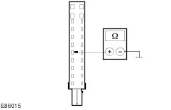
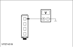
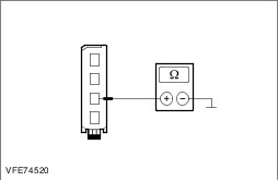
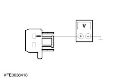
Trouble Code Table - Generic Electronic Module (GEM) | DTC | Description | Action | | 9D0613 | Circuit of left-hand turn signal lamps faulty. | REFER to: Turn Signal, Cornering and Hazard Lamps (417-01A Exterior Lighting, Diagnosis and Testing). | | 9D0611 | Circuit of left-hand turn signal lamps faulty (short to ground). | REFER to: Turn Signal, Cornering and Hazard Lamps (417-01A Exterior Lighting, Diagnosis and Testing). | | 91D311 | Circuit of left-hand side turn signal lamp faulty (short to ground). | REFER to: Turn Signal, Cornering and Hazard Lamps (417-01A Exterior Lighting, Diagnosis and Testing). | | 91D313 | Circuit of left-hand side turn signal lamp faulty (open circuit). | REFER to: Turn Signal, Cornering and Hazard Lamps (417-01A Exterior Lighting, Diagnosis and Testing). | | 9D0711 | Circuit of right-hand turn signal lamps faulty (short to ground). | REFER to: Turn Signal, Cornering and Hazard Lamps (417-01A Exterior Lighting, Diagnosis and Testing). | | 9D0713 | Circuit of right-hand turn signal lamps faulty. | REFER to: Turn Signal, Cornering and Hazard Lamps (417-01A Exterior Lighting, Diagnosis and Testing). | | 91CB11 | Circuit of right-hand side turn signal lamp faulty (short to ground). | REFER to: Turn Signal, Cornering and Hazard Lamps (417-01A Exterior Lighting, Diagnosis and Testing). | | 91CB13 | Circuit of right-hand side turn signal lamp faulty (open circuit). | REFER to: Turn Signal, Cornering and Hazard Lamps (417-01A Exterior Lighting, Diagnosis and Testing). | | 913C11 | Circuit of hazard warning switch illumination faulty (short to ground). | REFER to: Turn Signal, Cornering and Hazard Lamps (417-01A Exterior Lighting, Diagnosis and Testing). | | 913C15 | Circuit of hazard warning switch illumination faulty (short to voltage or open circuit). | REFER to: Turn Signal, Cornering and Hazard Lamps (417-01A Exterior Lighting, Diagnosis and Testing). | | 9D3524 | Circuit of hazard warning switch faulty. | REFER to: Turn Signal, Cornering and Hazard Lamps (417-01A Exterior Lighting, Diagnosis and Testing). | | 913007 | Light switch unit, component fault. | REFER to: Headlamps (417-01A Exterior Lighting, Diagnosis and Testing). | | 9D0011 | Circuit of left-hand headlamp faulty (short to ground). | REFER to: Headlamps (417-01A Exterior Lighting, Diagnosis and Testing). | | 9D0111 | Circuit of right-hand headlamp faulty (short to ground). | REFER to: Headlamps (417-01A Exterior Lighting, Diagnosis and Testing). | | 9D0013 | Circuit of left-hand headlamp faulty (open circuit). | REFER to: Headlamps (417-01A Exterior Lighting, Diagnosis and Testing). | | 9D0113 | Circuit of right-hand headlamp faulty (open circuit). | REFER to: Headlamps (417-01A Exterior Lighting, Diagnosis and Testing). | | 909811 | Circuit of left-hand marker lamp (side lamp) faulty (short to ground). | REFER to: Parking, Rear and License Plate Lamps (417-01A Exterior Lighting, Diagnosis and Testing). | | 909813 | Circuit of left-hand marker lamp faulty (side lamp) faulty (open circuit). | REFER to: Parking, Rear and License Plate Lamps (417-01A Exterior Lighting, Diagnosis and Testing). | | 909911 | Circuit of right-hand marker lamp (side lamp) faulty (short to ground). | REFER to: Parking, Rear and License Plate Lamps (417-01A Exterior Lighting, Diagnosis and Testing). | | 909913 | Circuit of right-hand marker lamp faulty (side lamp) faulty (open circuit). | REFER to: Parking, Rear and License Plate Lamps (417-01A Exterior Lighting, Diagnosis and Testing). | | 909B13 | Circuit of license plate lamps faulty. | REFER to: Parking, Rear and License Plate Lamps (417-01A Exterior Lighting, Diagnosis and Testing). | | 909B11 | Circuit of license plate lamps faulty (short to ground). | REFER to: Parking, Rear and License Plate Lamps (417-01A Exterior Lighting, Diagnosis and Testing). | | 9A7913 | Circuit of rear fog lamps faulty. | REFER to: Fog Lamps (417-01A Exterior Lighting, Diagnosis and Testing). | | 9A7911 | Circuit of rear fog lamps faulty (short to ground). | REFER to: Fog Lamps (417-01A Exterior Lighting, Diagnosis and Testing). | | 402311. 402313 | Stop lamp circuit faulty. | GO to Pinpoint Test A. | | 911511 | Circuit of high-mounted stop lamp faulty (short to ground). | GO to Pinpoint Test C. | | 911513 | Circuit of high-mounted stop lamp faulty (open circuit). | GO to Pinpoint Test B. | | 90AD09 | Rain sensor/light sensor, component fault. | REFER to: Autolamps (417-01A Exterior Lighting, Diagnosis and Testing), Wipers and Washers (501-16 Wipers and Washers, Diagnosis and Testing). | | 90AD04 | Internal circuit of rain sensor/light sensor faulty. | REFER to: Autolamps (417-01A Exterior Lighting, Diagnosis and Testing), Wipers and Washers (501-16 Wipers and Washers, Diagnosis and Testing). | Symptom Chart Symptom Chart | Symptom | Possible Sources | Action | | The stop lamps are inoperative. | * Fuse. * Circuit(s). * Stoplamp switch. * GEM | * | | One or more stop lamps not working. | * Circuit(s). * Tailgate lamp assembly. * Additional high-mounted stop lamp. * GEM | * | | One or more stop lamps permanently lit. | * Circuit(s). * Stoplamp switch. * GEM * Trailer Module. | * | Pinpoint test NOTE:Use a digital multimeter for all electrical measurements. | PINPOINT TEST A : THE STOPLAMPS ARE INOPERATIVE | | TEST CONDITIONS | DETAILS/RESULTS/ACTIONS | | A1: CHECK FUSE F28 (5 A) (CJB). | | | 1 Ignition switch in position 0. | | | 2 Disconnect fuse F28 (5 A) (CJB). | | | 3 CHECK fuse F28 (5 A) (CJB). | | | Is the fuse OK.? Yes No RENEW fuse F28 (5 A) (CJB) and CHECK the operation of the system. If the fuse blows again, LOCATE and RECTIFY the short using the Wiring Diagrams. CHECK system operates correctly | | A2: CHECK THE VOLTAGE SUPPLY TO FUSE F28 (5 A) (CJB) FOR OPEN CIRCUIT | | | 1 Connect fuse F28 (5 A) (CJB). | | | 2 Measure the voltage between fuse F28 (5 A) (CJB) and ground. | | | Does the meter display battery voltage? Yes No LOCATE AND RECTIFY the break in the voltage supply of fuse F28 (5 A) (CJB) with the aid of the Wiring Diagrams. CHECK system operates correctly | | A3: CHECK THE VOLTAGE SUPPLY TO THE STOPLAMP SWITCH FOR OPEN CIRCUIT | | | 1 Disconnect Stoplamp switch from connector C2CA29. | | | 2 Measure the voltage between the stoplamp switch, connector C2CA29, pin 1, circuit SBP28A (GN/RD), wiring harness side and ground. | | | Does the meter display battery voltage? Yes No | | A4: EXCLUDE THE GEM AS THE CAUSE OF THE FAULT | | | 1 Disconnect GEM from connector C1BP02-B. | | | 2 Measure the resistance between the stop lamp switch, connector C2CA29, pin 1, circuit SBP28A (GN/RD), wiring harness side and the GEM, connector C1BP02-B, pin 66, circuit SBP28A (GN/RD), wiring harness side. | | | Is a resistance of less than 2 Ohms registered? Yes INSTALL a new GEM. CHECK system operates correctly No LOCATE and RECTIFY break in circuit SBP28A (GN/RD) between the GEM and the stop lamp switch using the Wiring Diagrams. CHECK system operates correctly | | A5: EXCLUDE THE STOPLAMP SWITCH AS THE CAUSE OF THE FAULT | | | 1 Use a fused jumper lead (5 A) to connect the stop lamp switch, connector C2CA29, between pin 2, circuit CCA29C (GN/BU) and pin 1, circuit SBP28A (GN/RD), wiring harness side. | | | 2 Ignition switch in position II. | | | 3 CHECK the stop lamps. | | | Do the stoplamps come on? Yes RENEW brake light switch. CHECK system operates correctly No | | A6: CHECK THE CIRCUIT BETWEEN THE STOP LAMP SWITCH AND THE GEM FOR OPEN CIRCUIT | | | 1 Ignition switch in position 0. | | | 2 Disconnect GEM from connector C1BP02-B. | | | 3 Measure the resistance between the stop lamp switch, connector C2CA29, pin 2, circuit CCA29C (GN/RD), wiring harness side and the GEM, connector C1BP02-B, pin 54, circuit CCA29C (GN/BU), wiring harness side. | | | Is a resistance of less than 2 Ohms registered? Yes CHECK the GEM and INSTALL a NEW one if necessary. CHECK system operates correctly No LOCATE and RECTIFY break in circuit CCA29C (GN/BU) between the stop lamp switch and the GEM using the Wiring Diagrams. CHECK system operates correctly | | PINPOINT TEST B : ONE OR MORE STOPLAMPS ARE INOPERATIVE | | TEST CONDITIONS | DETAILS/RESULTS/ACTIONS | | B1: DETERMINE CONDITIONS UNDER WHICH THE FAULT OCCURS | | | 1 Ignition switch in position 0. | | | 2 Disconnect Stoplamp switch from connector C2CA29. | | | 3 Use a fused jumper lead (5 A) to connect the stoplamp switch, connector C2CA29, between pin 1, circuit SBP28A (GN/RD) and pin 2, circuit CCA29C (GN/BU), wiring harness side. | | | 4 Ignition switch in position II. | | | 5 CHECK the stop lamps. | | | Is only the high mounted stoplamp inoperative? Yes No - Left-hand stop lamp and additional high-mounted stop lamp inoperative: LOCATE and RECTIFY the break in the circuit GD150D (BK/WH) between soldered connection SP549 and ground connection G4D149 with the aid of the Wiring Diagrams. CHECK system operates correctly - Left-hand stop lamp and right-hand stop lamp inoperative: GO to B5. - Left-hand stop lamp inoperative: GO to B6. - Right-hand stop lamp inoperative: GO to B8. | | B2: CHECK THE VOLTAGE SUPPLY OF THE ADDITIONAL HIGH-MOUNTED STOPLAMP FOR OPEN CIRCUIT | NOTE:The fused jumper lead remains connected during this test step. | | | 1 Ignition switch in position 0. | | | 2 Disconnect Additional high-mounted stoplamp from connector C4LS50. | | | 3 Ignition switch in position II. | | | 4 Measure the voltage between the additional high-mounted stoplamp, connector C4LS50, pin 1, circuit CLS17A (YE/GY), wiring harness side and ground. | | | Does the meter display battery voltage? Yes No | | B3: CHECK THE GROUND CONNECTION OF THE ADDITIONAL HIGH-MOUNTED STOPLAMP FOR OPEN CIRCUIT | | | 1 Ignition switch in position 0. | | | 2 Measure the resistance between the additional high-mounted stoplamp, connector C4LS50, pin 2, circuit GD150J (BK/WH), wiring harness side and ground. | | | Is a resistance of less than 2 Ohms registered? Yes RENEW additional high-mounted stoplamp. CHECK system operates correctly No LOCATE and RECTIFY the break in circuit GD150J (BK/WH) between the additional high-mounted stop lamp and soldered connection SP534 using the Wiring Diagrams. CHECK system operates correctly | | B4: CHECK FOR OPEN CIRCUIT BETWEEN THE ADDITIONAL HIGH-MOUNTED STOP LAMP AND THE GEM | | | 1 Ignition switch in position 0. | | | 2 Disconnect GEM from connector C1BP02-B. | | | 3 Measure the resistance between the GEM, connector C1BP02-B, pin 49, circuit CLS17B (YE/GY), wiring harness side and the additional high-mounted stop lamp, connector C4LS50, pin 1, circuit CLS17A (YE/GY), wiring harness side. | | | Is a resistance of less than 2 Ohms registered? Yes INSTALL a new GEM. CHECK system operates correctly No LOCATE and RECTIFY the break in the circuit between GEM and the additional high-mounted stop lamp using the Wiring Diagrams. CHECK system operates correctly | | B5: CHECK THE SHARED POWER SUPPLY OF THE LEFT AND RIGHT-HAND STOPLAMPS FOR OPEN CIRCUIT | | | 1 Ignition switch in position 0. | | | 2 Disconnect GEM connector C1BP02-B. | | | 3 Measure the resistance between the GEM, connector C1BP02-B, pin 59, circuit CLS44F (VT/BN), wiring harness side and ground. | | | Is a resistance of less than 10,000 Ohm registered? Yes INSTALL a new GEM. CHECK system operates correctly No LOCATE and RECTIFY the break in circuit CLS44F (VT/BN) between the GEM and soldered connection SP451 with the aid of the Wiring Diagrams. CHECK system operates correctly | | B6: CHECK THE VOLTAGE SUPPLY OF THE LEFT-HAND STOPLAMP FOR OPEN CIRCUIT | NOTE:The fused jumper lead remains connected during this test step. | | | 1 Ignition switch in position 0. | | | 2 Disconnect Left-hand tailgate lamp assembly from connector C4LS18-A. | | | 3 Ignition switch in position II. | | | 4 Measure the voltage between left-hand tailgate lamp assembly, connector C4LS18-A, pin 1, circuit CLS44C (VT/BN), wiring harness side and ground. | | | Does the meter display battery voltage? Yes No LOCATE and RECTIFY the break in circuit CLS44C (VT/BN) between soldered connection SP451 and the tailgate lamp assembly with the aid of the Wiring Diagrams. CHECK system operates correctly | | B7: CHECK THE GROUND CONNECTION OF THE LEFT-HAND STOPLAMP FOR OPEN CIRCUIT | | | 1 Ignition switch in position 0. | | | 2 Measure the resistance between the left-hand tailgate lamp assembly, connector C4LS18-A, pin 3, circuit GD150C (BK/WH), wiring harness side and ground. | | | Is a resistance of less than 2 Ohms registered? Yes INSTALL A NEW tailgate lamp unit. CHECK system operates correctly No LOCATE and RECTIFY the break in circuit GD150C (BK/WH) between the tailgate lamp assembly and soldered connection SP549 using the Wiring Diagrams. CHECK system operates correctly | | B8: CHECK THE VOLTAGE SUPPLY OF THE RIGHT-HAND STOPLAMP FOR OPEN CIRCUIT | NOTE:The fused jumper lead remains connected during this test step. | | | 1 Ignition switch in position 0. | | | 2 Disconnect Right-hand tailgate lamp assembly from connector C4LS19-A. | | | 3 Ignition switch in position II. | | | 4 Measure the voltage between right-hand tailgate lamp assembly, connector C4LS19-A, pin 1, circuit CLS44A (VT/BN), wiring harness side and ground. | | | Does the meter display battery voltage? Yes No LOCATE and RECTIFY the break in circuit CLS44A (VT/BN) between soldered connection SP451 and the tailgate lamp assembly with the aid of the Wiring Diagrams. CHECK system operates correctly | | B9: CHECK THE GROUND CONNECTION OF THE RIGHT-HAND STOPLAMP FOR OPEN CIRCUIT | | | 1 Ignition switch in position 0. | | | 2 Measure the resistance between the right-hand tailgate lamp assembly, connector C4LS19-A, pin 3, circuit GD152A (BK/BU), wiring harness side and ground. | | | Is a resistance of less than 2 Ohms registered? Yes INSTALL A NEW tailgate lamp unit. CHECK system operates correctly No LOCATE and RECTIFY the break in circuit GD152A (BK/BU) between the tailgate lamp assembly and soldered connection SP600 using the Wiring Diagrams. CHECK system operates correctly | | PINPOINT TEST C : ONE OR MORE STOPLAMPS PERMANENTLY LIT | | TEST CONDITIONS | DETAILS/RESULTS/ACTIONS | | C1: DETERMINE CONDITIONS UNDER WHICH THE FAULT OCCURS | | | 1 Ignition switch in position 0. | | | 2 CHECK the stop lamps. | | | Are all stoplamps permanently lit? Yes No - Only the additional high-mounted stop lamp is permanently lit: GO to C4. - Only the left and right stop lamps are permanently lit: GO to C5. | | C2: EXCLUDE THE STOPLAMP SWITCH AS THE CAUSE OF THE FAULT | | | 1 Ignition switch in position 0. | | | 2 Disconnect Stoplamp switch from connector C2CA29. | | | 3 Ignition switch in position II. | | | 4 CHECK the stop lamps. | | | Are all stoplamps permanently lit? Yes No RENEW brake light switch. CHECK system operates correctly | | C3: CHECK CONTROL CIRCUIT BETWEEN STOP LAMP SWITCH AND THE GEM FOR SHORT TO BATTERY VOLTAGE | | | 1 Ignition switch in position 0. | | | 2 Disconnect GEM from connector C1BP02-B. | | | 3 Ignition switch in position II. | | | 4 Measure the voltage between the stoplamp switch, connector C2CA29, pin 2, circuit CCA29C (GN/BU), wiring harness side and ground. | | | Does the meter display battery voltage? Yes LOCATE and RECTIFY the short to battery voltage in the circuit between the stop lamp switch and the GEM using the Wiring Diagrams. CHECK system operates correctly No CHECK the GEM and INSTALL a NEW one if necessary. CHECK system operates correctly If the concern persists: | | C4: CHECK CIRCUIT BETWEEN THE GEM AND THE ADDITIONAL HIGH-MOUNTED STOP LAMP FOR SHORT TO BATTERY VOLTAGE | | | 1 Ignition switch in position 0. | | | 2 Disconnect GEM from connector C1BP02-B. | | | 3 Ignition switch in position II. | | | 4 CHECK the high mounted stoplamp. | | | Is the additional high-mounted stoplamp permanently lit? Yes LOCATE and RECTIFY the short to battery voltage in the circuit between the GEM and the additional high-mounted stop lamp using the Wiring Diagrams. CHECK system operates correctly No INSTALL a new GEM. CHECK system operates correctly If the concern persists: | | C5: CHECK THE CIRCUIT BETWEEN THE GEM AND THE LEFT AND RIGHT-HAND STOP LAMPS FOR SHORT TO BATTERY VOLTAGE | | | 1 Ignition switch in position 0. | | | 2 Disconnect GEM from connector C1BP02-B. | | | 3 Ignition switch in position II. | | | 4 CHECK the stop lamps. | | | Are only the left and right stoplamps permanently lit? Yes - Vehicles without trailer socket: Use the Wiring Diagrams to LOCATE and RECTIFY the short to battery voltage in the circuits connected to soldered connection SP451. CHECK system operates correctly - Vehicles with a trailer socket: GO to C6. No INSTALL a new GEM. CHECK system operates correctly If the concern persists: | | C6: EXCLUDE THE TRAILER MODULE AS THE CAUSE OF THE FAULT | | | 1 Ignition switch in position 0. | | | 2 Disconnect fuse FA11 (40 A) (RJB). | | | 3 Ignition switch in position II. | | | 4 CHECK the stop lamps. | | | Are only the left and right stoplamps permanently lit? Yes Use the Wiring Diagrams to LOCATE and RECTIFY the short to battery voltage in the circuits connected to soldered connection SP451. CHECK system operates correctly No RENEW the trailer module. CHECK system operates correctly | |