
Mustang V8-5.4L SC VIN S (2007)
4. CAUTION:
-
Putting the large RCM electrical wiring connector into the RCM on an angle can cause bad electrical connections and damage
components.
-
Do not push the connector to where the lever pivots and seats itself. Light pressure is needed to get the connector into position on the
RCM before using the lever to fully seat the connector.
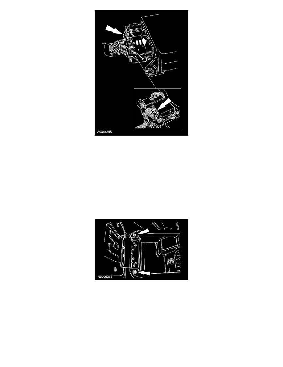
NOTE: A similar RCM and connectors are shown.
Connect the large RCM electrical wiring connector.
-
Using the connector position assurance lever, pivot it toward the RCM, drawing the connector into the RCM.
-
Make sure the thumb tab is engaged to the retainer on the RCM and locked in place.
5. Connect the electrical connectors and install the center instrument panel finish panel and the 6 screws.
6. Install the driver and passenger center console kick panels.
7. Install the center console top finish panel and the 2 screws.