
Mustang Cobra V8-281 4.6L DOHC VIN V MFI (1997)
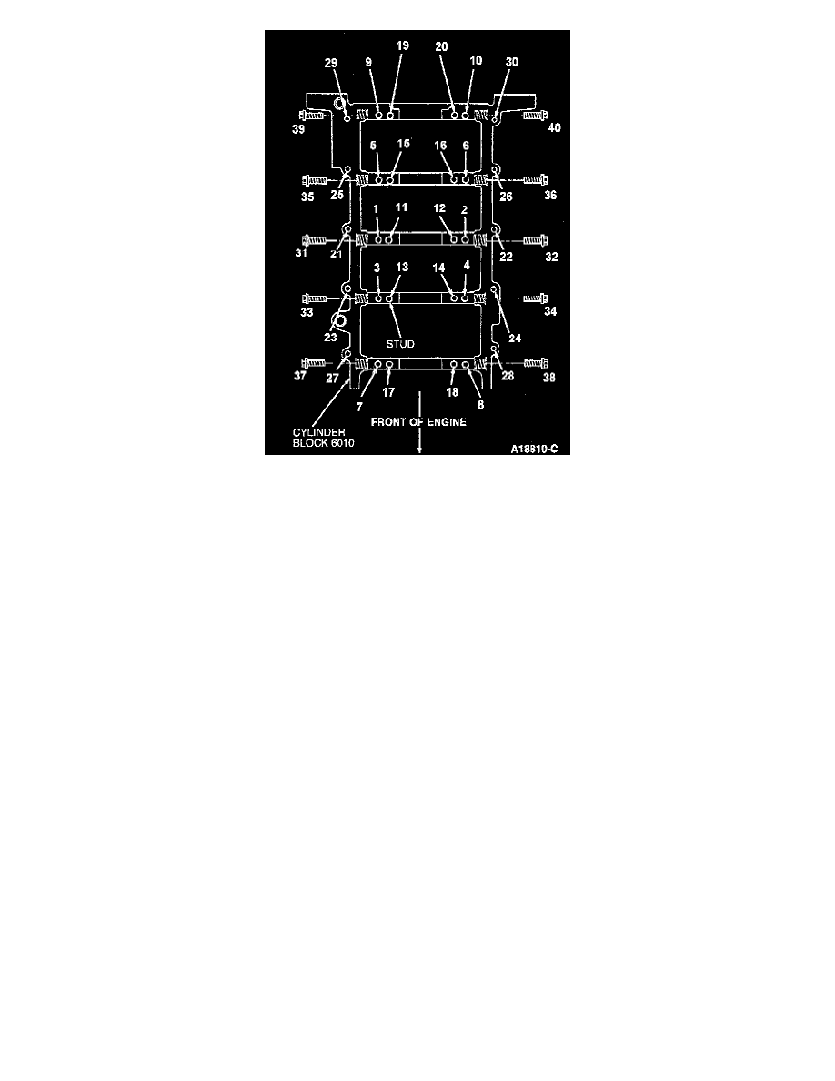
7. Tighten in sequence the vertical main bolts in positions 1 through 8 to 8-12 Nm (71-106 inch lbs.). Then tighten vertical main bolts in positions 10
through 18 to 8-12 Nm (71-106 inch lbs.).
8. Push crankshaft forward and wedge using a prybar or similar tool to seat crankshaft thrust washer.
NOTE: No.5 main bearing cap must be seated above until the main bearing cap bolts are fully tightened as required according to the following
procedure.
9. With crankshaft wedged forward, use prybars or similar tools to wedge both RH and LH front edges of No. 5 main bearing cap rearward to
position the lower crankshaft thrust main bearing rear face properly against the thrust face of the crankshaft.
NOTE: Wedge crankshaft in direction of arrow to fully seat crankshaft thrust washer. Leave prybars in position until all main bearing bolts are
tightened.
10. Tighten vertical main bolts 9,10,19 and 20 to 8-12 Nm (71-106 inch lbs.) in order.
11. Tighten vertical main bolts 1 through 10 to 22-28 Nm (17-20 ft. lbs.).
12. Tighten vertical main bolts 11 through 20 to 37-43 Nm (28-31 ft. lbs.).
13. Rotate vertical main bolts 1 through 20, turning clockwise, 85-95°.
14. Remove all wedges from No.5 main cap and from crankshaft.
15. Tighten crankshaft main bearing cap adjusting screws, positions 21 through 30, in sequence to 5 Nm (44 inch lbs.). Retighten crankshaft main
bearing cap adjusting screw in sequence to 10 Nm (88 inch lbs.).
16. Tighten main cap side bolts, positions 31 through 40, in sequence in two steps: 10 Nm (88 inch lbs.), then 19-23 Nm (14-17 ft. lbs.).
NOTE: Pry against No.2 main bearing cap.