
Probe V6-153 2.5L DOHC (1994)
2.
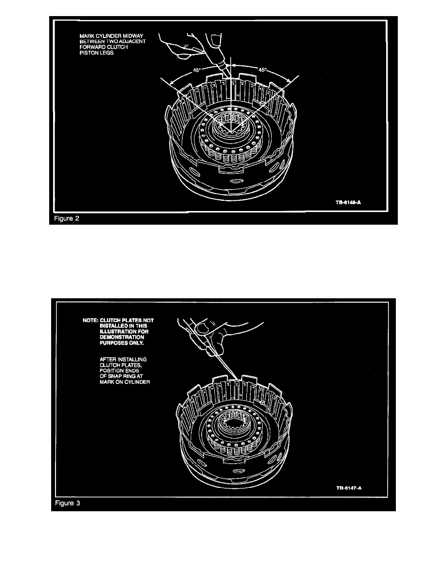
Mark the top of the cylinder with a felt tip marker midway between any two adjacent legs (i.e., 45 degrees or 4 external spline teeth from the
center of any leg) (Figure 2).
NOTE:
THE FORWARD PISTON LEGS WILL NO LONGER BE VISIBLE WHEN CLUTCH PACK AND RETAINER IS INSTALLED.
3.
Following the Service or Workshop Manual procedure, install the clutch plates.
4.
Position the ends of the snap ring such that the gap is aligned with the mark on the top of the cylinder (the 45 degree mark) (Figure 3).
5.
Perform end clearance check as required.
OTHER APPLICABLE ARTICLES: NONE