
Probe V6-153 2.5L DOHC (1994)
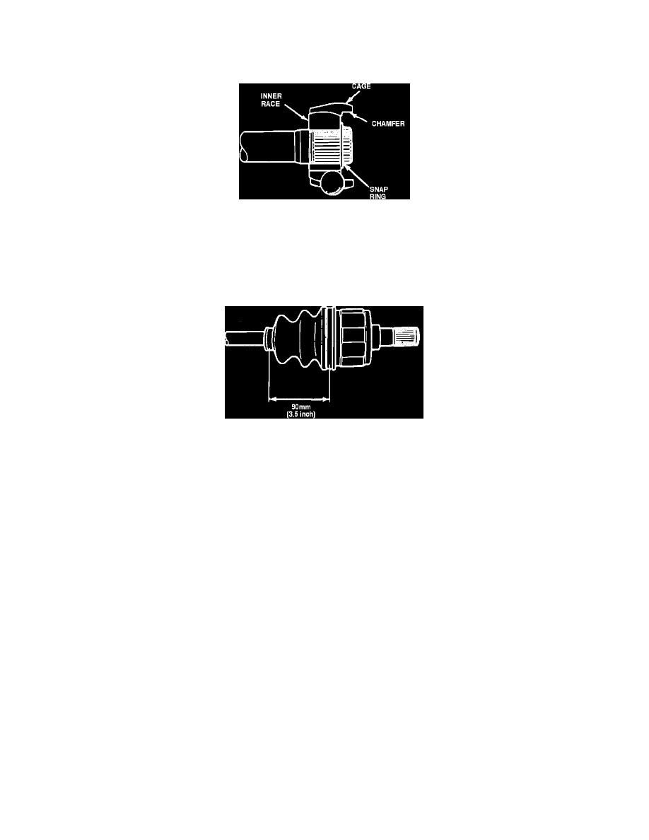
Fig. 13 Positioning Inner Bearing Race To Cage
16.
Aligning mark made during disassembly, position inner race into bearing cage. Inner race chamfered splines should face large end of cage.
17.
Using hand pressure, press ball bearings into cage windows.
Fig. 14 Positioning Bearing Cage To Halfshaft
18.
Aligning marks on inner race and halfshaft made during disassembly, position inner race, cage and ball bearing assembly onto halfshaft, then insert
snap ring into halfshaft groove. When install bearing assembly on halfshaft, chamfered end of cage should face snap ring.
19.
Apply 1.4 to 2.1 ounces of lubricant E43Z-19590-A or equivalent to outer race, then install outer race over inner race, cage and ball bearing
assembly.
20.
Add approximately 0.7 to 1 ounce of lubricant to outer race, then install outer race bearing retaining ring.
Fig. 15 Position Constant Velocity Joint On Halfshaft
21.
Seat boot in grooves on halfshaft and outer race, then extend constant velocity joint until distance between boot grooves is 3 1/2 inches. Keep joint
at this distance until after boot clamps have been installed.
22.
Using a screwdriver with sharp edges filed off, pry up on boot at outer race to allow trapped air to escape.
23.
Install and lock boot clamps.
24.
Check constant velocity joint for smoothness of operation through its full range of travel.
25.
Install halfshaft on vehicle.