| Diagnosis and Testing Special Tool(s) | | Pressure Tester, Cooling System 303-396 (24-001A) | | | Adapter for 303-396 303-396-01 | General Equipment Worldwide Diagnostic System (WDS) Inspection and Verification - Verify the customer concern.
- Visually inspect for obvious signs of mechanical or electrical damage.
Visual Inspection Chart | Mechanical | Electrical | - Coolant leak(s)
- Coolant level
- Air in system
- Gaskets/seals
- Hose(s)/hose joints
- Coolant expansion tank cap and seal
- Coolant expansion tank
- Radiator
- Water pump
- Thermostat
- Thermostat housing
- Accessory drive belt
| - Fuse(s)
- Relay(s)
- Wiring harness
- Electrical connector(s)
- Cooling fan motor
- Engine coolant temperature (ECT) sensor
- Powertrain control module (PCM)
| - If an obvious cause for an observed or reported concern is found, correct the cause (if possible) before proceeding to the next step.
- If the cause is not visually evident, verify the symptom and refer to the Symptom Chart.
Symptom Chart Symptom Chart | Symptom | Possible Sources | Action | | Loss of coolant | * Hose(s)/hose joint(s). | * INSPECT the hoses and hose joints. INSTALL a new hose(s) as necessary. | | * Radiator. | * INSPECT the radiator for leaks. CARRY OUT the Pressure Test Component Test in this section. INSTALL a new radiator as necessary.
REFER to: Radiator (303-03 Engine Cooling, Removal and Installation).
| | * Water pump. | * INSPECT the water pump for leaks. CARRY OUT the Pressure Test Component Test in this section. INSTALL a new water pump or water pump gasket as necessary.
REFER to: Water Pump (303-03 Engine Cooling, Removal and Installation).
| | * Thermostat housing. | * INSPECT the thermostat housing for leaks. CARRY OUT the Pressure Test Component Test in this section. INSTALL a new thermostat housing or thermostat housing gasket as necessary.
REFER to: Thermostat (303-03 Engine Cooling, Removal and Installation).
| | * Coolant expansion tank cap or seal. | * CHECK the coolant expansion tank cap for tightness. If OK, CARRY OUT the Coolant Expansion Tank Cap Pressure Test Component Test in this section. | | * Coolant expansion tank. | * INSPECT the seal face on the coolant expansion tank for damage. INSTALL a new coolant expansion tank as necessary. | | * Heater core. | * CHECK the heater core for leaks. | | * Engine. | * INSPECT the engine, cylinder head, cylinder block and cylinder head gasket.
REFER to: Cylinder Head (303-01A Engine - 1.7L, In-vehicle Repair) /
Cylinder Head (303-01A, In-vehicle Repair) /
Cylinder Head (303-01B Engine - 1.4L Zetec-SE (Sigma)/1.6L, In-vehicle Repair).
| | The engine overheats (signs of coolant boiling) | * Cooling system does not hold pressure. | * CARRY OUT the Coolant Expansion Tank Cap Test Component Test in this section. * INSPECT the coolant expansion tank for damage. INSTALL a new coolant expansion tank as necessary. * INSPECT the water pump or water pump gasket for damage. INSTALL a new water pump or water pump gasket as necessary.
REFER to: Water Pump (303-03 Engine Cooling, Removal and Installation).
* INSPECT the engine, cylinder head, cylinder block and cylinder head gasket.
REFER to: Cylinder Head (303-01A Engine - 1.7L, In-vehicle Repair) /
Cylinder Head (303-01A, In-vehicle Repair) /
Cylinder Head (303-01B Engine - 1.4L Zetec-SE (Sigma)/1.6L, In-vehicle Repair).
| | * Radiator. | * INSPECT the radiator for blockage or damage. CARRY OUT the Pressure Test Component Test in this section. INSTALL a new radiator as necessary.
REFER to: Radiator (303-03 Engine Cooling, Removal and Installation).
| | * Air in system. | * BLEED the cooling system.
REFER to: Cooling System Draining, Filling and Bleeding (303-03 Engine Cooling, General Procedures).
| | * Coolant expansion tank cap or seal. | * CHECK the coolant expansion tank cap for tightness. If OK, CARRY OUT the Coolant Expansion Tank Cap Pressure Test Component Test in this section. | | * Coolant expansion tank. | * INSPECT the seal face on the coolant expansion tank for damage. INSTALL a new coolant expansion tank as necessary. | | * Coolant level/condition. | * CHECK the coolant level. REFILL the cooling system as necessary.
REFER to: Cooling System Draining, Filling and Bleeding (303-03 Engine Cooling, General Procedures).
* CHECK the coolant condition. If the coolant is in poor condition drain and refill with new coolant.
REFER to: Cooling System Draining, Filling and Bleeding (303-03 Engine Cooling, General Procedures).
| | * Coolant concentration. | * REFER to: Specifications (303-03 Engine Cooling, Specifications). | | * Radiator grille. | * INSPECT the radiator grille for air restrictions or damage. REPAIR or INSTALL new parts as necessary. | | * Water pump. | * CARRY OUT the Pressure Test Component Test in this section. INSPECT the water pump for leaks. INSTALL a new water pump or water pump gasket as necessary.
REFER to: Water Pump (303-03 Engine Cooling, Removal and Installation).
| | * Thermostat. | * CARRY OUT the Thermostat Test Component Test in this section. INSTALL a new thermostat as necessary.
REFER to: Thermostat (303-03 Engine Cooling, Removal and Installation).
| | * Accessory drive belt | * CHECK the accessory drive belt for correct operation.
REFER to: Accessory Drive (303-05 Accessory Drive, Diagnosis and Testing).
| | * Cooling fan motor. | * CHECK the operation of the cooling fan motor. REFER to WDS/FDS 2000. | | * Engine. | * INSPECT the engine, cylinder head, cylinder block and cylinder head gasket.
REFER to: Cylinder Head (303-01A Engine - 1.7L, In-vehicle Repair) /
Cylinder Head (303-01A, In-vehicle Repair) /
Cylinder Head (303-01B Engine - 1.4L Zetec-SE (Sigma)/1.6L, In-vehicle Repair).
| | The engine does not reach normal operating temperature. | * Thermostat. | * CARRY OUT the Thermostat Test Component Test in this section. INSTALL a new thermostat as necessary.
REFER to: Thermostat (303-03 Engine Cooling, Removal and Installation).
| | Cooling fan not working/ continuously working | * Relay. * Thermostat. * Cooling fan. | * Refer to WDS/FDS 2000. | Component Tests Pressure Test WARNING:When releasing the system pressure, cover the expansion tank cap with a thick cloth to prevent the possibility of coolant scalding, Failure to follow this instruction may result in personal injury. - Remove the coolant expansion tank cap.
- Install the special tools to the coolant expansion tank.
- Pressurize the system to the coolant expansion tank cap release pressure.
REFER to: Specifications (303-03 Engine Cooling, Specifications).
- Observe the cooling system pressure tester gauge reading for approximately two minutes. The pressure should not drop during this time. If the system holds pressure, proceed to step 6. If the system does not hold pressure, check it thoroughly for coolant leaks.
- Check the engine for coolant leaks. Drain the cooling system, repair any coolant leaks found and fill and bleed the cooling system as necessary.
REFER to: Cooling System Draining, Filling and Bleeding (303-03 Engine Cooling, General Procedures).
- Recheck the system by repeating steps 3 and 4 at least twice.
Radiator Leak Test, Removed From Vehicle CAUTION:Radiator internal pressure must not exceed 130 kpa (20 psi) or damage may result. Clean the radiator thoroughly before leak testing it, to prevent contamination of the water in the test tank. Leak test the radiator in clean water with 138 kpa (20 psi) air pressure. Check it thoroughly for air leaks. INSTALL a new radiator if necessary.
REFER to: Radiator (303-03 Engine Cooling, Removal and Installation).
Coolant Expansion Tank Cap Pressure Test WARNING:When releasing the system pressure, cover the expansion tank cap with a thick cloth to prevent the possibility of coolant scalding, Failure to follow this instruction may result in personal injury. - Remove the coolant expansion tank cap.
- Use water to clean the area of the rubber seal and pressure relief valve. Install the pressure tester and adapter and immerse the coolant expansion tank cap in water .
NOTE:If the plunger of the pump is depressed too quickly, an erroneous pressure reading will result. - Slowly depress the plunger of the pressure test pump until the pressure gauge reading stops increasing, and note the highest pressure reading obtained.
- Release pressure by turning the pressure relief screw counterclockwise. Tighten the pressure relief screw and repeat step 3 at least twice to make sure the pressure test reading is repeatable and within acceptable gauge reading limits of the coolant expansion tank cap.
- If the pressure test gauge readings are not within the acceptable gauge reading limits, INSTALL a new coolant expansion tank cap.
Thermostat Test - Using the WDS datalogger function, SELECT the following sensors (as applicable to the application):
- IAT - intake air temperature (IAT) sensor
- ECT - engine coolant temperature (ECT) sensor
- CHT - cylinder head temperature (CHT) sensor
- LOAD - engine load
- VSS - vehicle speed sensor (VSS)
- RPM - engine speed
- DSRPM - desired engine speed
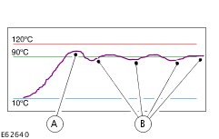
The IAT sensor output is useful if the engine being tested is cold or after an over-night cold soak. The ECT sensor or CHT sensor and the IAT sensor should either indicate the same value or be within 1 to 2 degrees Celsius of each other. The ECT sensor output is important to display as it indicates the engine warm-up and opening temperature for the thermostat. It will initially indicate a slightly higher reading just before the thermostat opens and then drops back before settling to a near flat line output (see graphic below). B - Thermostat settles into a cyclic open and closure pattern CAUTION:If the ECT sensor output reaches the 120ºC default line under normal cooling system pressure, internal damage may be caused to the engine and a diagnostic trouble code (DTC) will be set in the PCM. The test should be stopped and the cause located and corrected. If the cooling system does not pressurize, the coolant will boil at 100ºC which may also damage the engine. CARRY OUT the Coolant Expansion Tank Cap Pressure Test Component Test in this section. If the WDS only allows the ECT sensor to be displayed in volts, refer to the following table for corresponding Celsius values: | Volts | ºCelsius | | 1.33 | 60 | | 1.02 | 70 | | 0.78 | 80 | | 0.60 | 90 | | 0.46 | 100 | | 0.35 | 110 | | 0.27 | 120 | The CHT sensor output is useful to examine the cylinder head temperature rise during the warm-up cycle and later during the normal light throttle cruise test. This sensor output may vary between vehicles with manual transmission and vehicles with automatic transmission and should be used for reference only. The LOAD display is used for reference as it is necessary to maintain a stable load line during the test. It is necessary to carry out the test under normal light throttle cruise driving conditions and average loads, typically 40% to 70% of the load value. The VSS output is used for reference but can help to identify misfires and sensors which fail during the warm-up cycle. The RPM display indicates the engine speed and can be compared with the DSRPM. The DSRPM is the desired or calculated idle speed which the PCM commands the engine to reach. If the thermostat opens too early (before the correct opening temperature has been reached), the engine will not reach this value. When using the WDS in data logger mode, the signals recorded should remain within the DEFAULT values set by the WDS. -
WARNING:Make sure that the WDS is placed in the vehicle so that it does not interfere with the safe operation of the vehicle. Do not place the WDS in the deployment path of any air bag. Failure to follow these instructions may result in personal injury. NOTE:The road test is best carried out with the aid of another technician in the vehicle to enable the vehicle to be driven safely while the sensor outputs are monitored within datalogger. If there is only one technician available, the WDS can be set up (using the record/capture mode camera icon) before leaving the workshop to record a 16 km (10 mile) test. NOTE:The results from the test are more conclusive if the engine is cold when the test is started. Carry out a road test.
REFER to: Road/Roller Testing (100-00 General Information, Description and Operation).
- Drive the vehicle at a constant throttle opening and set speed until the ECT value settles into a shallow rise and fall signal, close to a straight line. This indicates that the thermostat is functioning correctly.
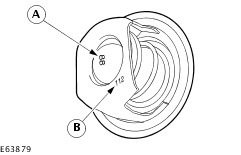
NOTE:Some thermostats indicate the temperature(s) in Celsius and Fahrenheit. The graphic below shows the location and an example of the opening temperature (88ºC) and fully open temperature (102ºC) of a thermostat. The graphic below shows an alternative method used to show the opening temperature (88ºC) and fully open temperature (112ºC) of a thermostat. NOTE:Generally, most thermostats maintain a coolant temperature between 88ºC (190ºF) and 92ºC (198ºF) although dual stage electric thermostats may increase the coolant temperature up to 100ºC (212ºF) under light engine load conditions. The engine should start cleanly and the ECT value will rise quite quickly with smooth progression. If the ECT signal appears unstable or erratic, the ECT sensor, electrical connector and wiring harness to the PCM need to be visually inspected for damage, chafing or water ingress. The temperature should rise to approximately 90ºC for a thermostat that has an 88ºC value. The signal value will then fall as cooler coolant enters the engine. If the ECT value fails to maintain a constant value and falls back to lower figures, typically between 60ºC (140ºF) and 70ºC (150ºF), the thermostat and its sealing function within the thermostat housing must be checked. - INSTALL a new thermostat.
REFER to: Thermostat (303-03 Engine Cooling, Removal and Installation).
- Carry out another road test from step 1 using the same criteria to confirm that the concern has been rectified.
- Using the WDS, clear the PCM keep alive memory (KAM) or electrically erasable programmable read only memory (EEPROM) so that new drive values can be learnt.
|