| Disassembly and Assembly of Subassemblies Special Tool(s) | | Compressor, Clutch Spring 307-015 | | | Protector, Piston Seal 307-049 | Materials Name Specification Transmission Fluid MERCON® Overdrive Brake and Coast Clutch Drum Component 2 - Coast clutch piston outer seal ring 3 - Coast clutch piston inner seal ring 5 - Overdrive piston spring 6 - Coast clutch piston spring retainer 8 - Coast clutch external spline plate (steel) 9 - Coast clutch internal spline plate (friction) 10 - Coast clutch pressure plate 11 - Retaining ring (select fit) Disassembly | | -
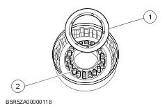
Remove the coast clutch pressure plate. - Remove the retaining ring.
- Remove the coast clutch pressure plate.
| | | -
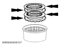
WARNING:Use caution when releasing tool pressure on the piston spring. Failure to follow these instructions may result in personal injury. CAUTION:Do not fully compress the SST or damage to the spring retainer may occur. Remove the coast clutch disc pack. - Inspect for wear, install a new pack as necessary.
| | | -
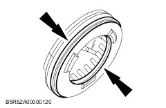
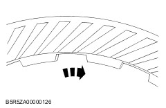
Using the SST, remove the retaining ring. | | -
Relieve the coast clutch spring tension and remove the SST. | | | -
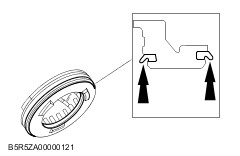
WARNING:Air pressure must not exceed 138 kPa {1.4 kgf/cm2, 20 psi}. Wear safety glasses when using compressed air and make sure the drum is facing down as shown. Failure to follow these instructions may result in personal injury. Remove the coast clutch piston springs. - Remove the coast clutch piston spring retainer.
- Remove the coast clutch piston springs.
| | | -
Remove the coast clutch piston. - Apply air pressure to the hole in the drum to remove the coast clutch piston while blocking the other hole with a finger.
| | | -
Remove and discard the coast clutch piston inner seal and the coast clutch piston outer seal. | Assembly | | -
CAUTION:The lip seals must be positioned as shown. Care must be taken to prevent rollover of the lip seal. Install the new coast clutch piston inner and outer seal. | | | -
CAUTION:Care must be taken to prevent damage to the seals during installation. Verify the check ball is free to move. | | | -
Using the SST, install the coast clutch piston. - Lubricate the seals with transmission fluid.
| | | -
CAUTION:Do not fully compress the SST or damage to the coast clutch piston spring retainer may occur. Install the coast clutch piston springs. - Install the coast clutch piston springs.
- Install the coast clutch piston spring retainer.
| | | -
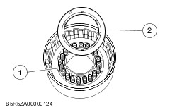
CAUTION:Coast clutch friction plates are directional and must be installed with grooves clockwise (ID to OD). The word TOP should face up. CAUTION:If new clutch plates are being used, they should be soaked in clean ATF before assembly. Using the SST, install the spring retainer ring. | | | -
When installing friction plates, the word TOP should face up. If reusing plates, grooves must be installed clockwise. Install the coast clutch disc pack. | | | -
CAUTION:The retaining ring is select fit. Install the 2 steel clutch plates and 2 friction clutch plates in alternating order starting with a steel clutch plate. | | | -
WARNING:Air pressure must not exceed 138 kPa {1.4 kgf/cm2, 20 psi}. Wear safety glasses when using compressed air and make sure drum is facing down as shown. Failure to follow these instructions may result in personal injury. Install the coast clutch pressure plate. - Install the coast clutch pressure plate.
- Install the original retaining ring.
| | | -
Air check the assembly. - Apply air pressure to the hole in the drum while blocking the other hole with a finger.
| | | -
Check the coast clutch disc pack free play. - Push down on the coast pressure plate.
- Check clearance between the coast clutch retaining ring and coast pressure plate. Clearance should be 1.3—2.0 mm {0.051— 0.079 in}. If clearance is not within the specification, install a correct coast clutch retaining ring that will provide the correct free play adjustment.
- Coast clutch clearance Standard: 1.3—2.0 mm {0.051—0.079 in}
| | | -
Retaining ring size for coast clutch clearance | Thickness | Diameter | | mm | in | mm | in | | 1.37 | 0.0539 | 130.1 | 5.122 | | 1.73 | 0.0681 | 130.1 | 5.122 | | 2.08 | 0.0819 | 130.1 | 5.122 | | 2.44 | 0.0961 | 130.1 | 5.122 | | |