| Disassembly Special Tool(s) | | Slide Hammer 100-001 | | | Holding Fixture, Transmission 307-003 | | | Handle, Torque Converter 307-091 | | | Remover, Torque Converter Fluid Seal 307-309 | | | Remover, Transmission Fluid Pump 303-397 | | | Compressor, Servo Cover 307-402 | | | Installer, Transmission Extension Housing Oil Seal 308-375 | Disassembly 1 - Torque converter installation nut 8 - Fluid pump adapter plate 14 - Fluid pump control valve 19 - Intermediate and overdrive brake band anchor strut 20 - Intermediate and overdrive brake band 21 - Intermediate and overdrive brake band apply strut 22 - Intermediate and overdrive brake band adjusting screw 25 - Direct clutch and coast clutch piston outer seals 26 - Direct clutch and coast clutch piston inner seals 27 - Direct clutch and coast clutch pistons 28 - Direct clutch and coast clutch piston spring 29 - Direct clutch and coast clutch piston spring retainer 31 - Coast clutch external spline plate (steel) 32 - Coast clutch internal spline friction plate (friction) 33 - Direct clutch and coast clutch pressure plate 34 - Retaining ring (select fit) 37 - Overdrive planetary gear carrier component 40 - Overdrive one-way clutch 43 - Overdrive center shaft and ring gear component 44 - Thrust bearing (No.3, No.5, No.8 and No.9) 50 - Intermediate brake drum 51 - Direct clutch external spline plate (steel) 52 - Direct clutch internal spline plate (friction) 53 - Forward clutch cylinder 55 - Forward clutch piston spring component 57 - Forward clutch external spline plate (steel) 58 - Forward clutch internal spline plate (friction) 59 - Forward clutch pressure plate 60 - Retaining ring (select fit) 67 - Forward planetary component 68 - Input shell and sun gear component 71 - Lower/reverse planetary component 79 - Low/reverse brake drum and one-way clutch component 81 - Output shaft needle bearing 86 - Parking pawl return spring 88 - Extension housing gasket 89 - Extension housing (4x2) 91 - Extension housing seal (4x2) 93 - Extension housing (4x4) 94 - Extension housing seal (4x4) 96 - Oil pipe connector component 98 - Overdrive brake servo cover seal 99 - Overdrive brake servo cover 100 - Overdrive brake servo piston 103 - Intermediate brake servo cover seal 104 - Intermediate brake servo cover 105 - Intermediate brake servo piston 107 - TSS sensor, ISS sensor and OSS sensor 111 - Low/reverse brake actuating lever 112 - Low/reverse brake band actuating lever shaft 113 - Pressure tap plug (pressure control solenoid C circuit) 115 - Manual shaft retaining pin 116 - Parking pawl actuating rod 117 - Manual shaft outer and inner nut 118 - Manual valve inner lever 121 - Digital transmission range (TR) sensor 124 - Reverse brake servo component 125 - Reverse brake servo plate 127 - Reverse brake servo piston and sealReverse brake servo piston and seal 129 - Reverse brake servo cover 131 - Control valve spring retainer 133 - Reverse brake servo check valve 135 - Separating plate (bonded) 136 - Lower control valve body 142 - Control valve body component 147 - Transmission fluid filter 148 - Transmission fluid pump gasket 151 - Transmission fluid pump 154 - Fluid level indicating plug (short hex) 155 - Overdrive brake and coast clutch drum component 156 - Intermediate brake and direct clutch drum component 157 - Forward clutch component 159 - Intermediate brake servo NOTE:Tag and identify all parts during disassembly. | | -
Place the transmission on a workbench. | | | -
WARNING:The torque converter is heavy, especially when full of fluid. Using the SSTs, remove the torque converter. | | | -
Using the SST, install the transmission into the bench with the torque converter housing facing up. | | | -
Remove the manual shaft lever. | | | -
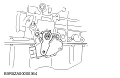
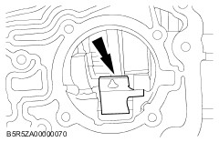
Remove the digital transmission range (TR) sensor. | | | -
Using the SST, remove the extension housing seal. (4x2). | | | -
CAUTION:The parking pawl, parking pawl return spring and parking pawl shaft could fall out during removal of the extension housing. Remove the extension housing. (4x2). | | | -
Using the SSTs, remove the extension housing seal. (4x4). | | | -
CAUTION:The parking pawl, parking pawl return spring and parking pawl shaft could fall out during removal of the extension housing. NOTE:4x2 shown, 4x4 similar. Remove the extension housing (4x4). | | | -
Remove the parking pawl component and discard the gasket. - Remove the parking pawl shaft.
- Remove the parking pawl.
- Remove the parking pawl return spring.
- Remove and discard the gasket.
| | | -
NOTE:The transmission fluid pan gasket is reusable. Clean and inspect the gasket for damage. If not damaged, the gasket should be reused. Remove the screws, transmission fluid pan and gasket. | | | -
Remove the transmission fluid filter and seal component and discard. | | | -
WARNING:The upper and lower servo covers are under spring tension. Use care when removing the piston and cover component. Failure to follow these instructions can result in personal injury. Remove the detent spring. | | | -
Remove the low/reverse brake servo component. | | | -
CAUTION:Do not damage solenoid body connector pins. Remove the solenoid body component by lifting on the body and pushing the connector from the other side of the case. | | | -
Remove the main control valve body, separator plate and gasket. | | | -
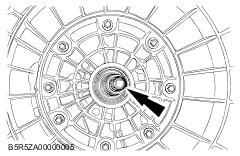
Using the SST, remove the fluid pump seal. | | | -
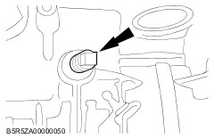
CAUTION:Failure to loosen the overdrive brake band adjusting screw prior to pump removal may cause damage to the pump and overdrive brake band. CAUTION:Throw the locknut away. The locknut are not reusable for assembly. Remove and discard the locknut, and loosen the overdrive brake band adjusting screw. | | | -
Remove and tag the overdrive brake band anchor strut for assembly. | | | -
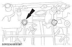
CAUTION:The screws are not reusable for assembly. Discard the screws. If the screws are reused, the housing may become separated from the transmission. Remove and discard the screws. | | | -
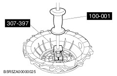
Using the SST, remove the fluid pump. | | | -
CAUTION:Servo cover is under spring tension. Using the SST, remove the retaining ring and overdrive brake servo cover. | | | -
Remove the overdrive brake servo piston and spring. | | | -
Compress the overdrive brake band and remove the apply strut. | | | -
CAUTION:Identify the anchor and apply ends of the overdrive brake band. NOTE:Tag and identify parts for reassembly. NOTE:The new overdrive brake band is dark in color. This is a normal condition of the band. Hairline cracks in the band are also considered normal. Do not install a new band based solely on the color. Remove and inspect the overdrive brake band. Check the following conditions for installing a new band: - Inspect for glazing.
- Inspect for missing friction material.
- Inspect for material flaking.
- Inspect for damage to the anchor pins.
| | | -
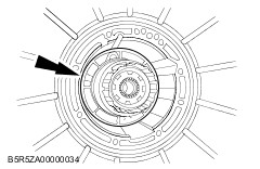
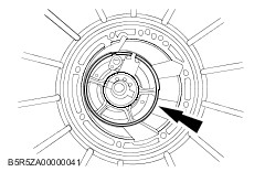
Remove the overdrive brake and coast clutch drum component. | | | -
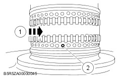
CAUTION:Do not bend the trigger wheel. NOTE:The thrust bearing (No.12) is in this component. Remove the overdrive planetary gear carrier. | | | -
Remove the thrust bearing (No.2). | | | -
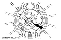
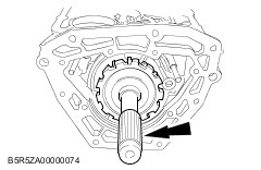
Remove the overdrive ring gear, overdrive oneway clutch component and center shaft as an assembly. | | | -
NOTE:Tag and identify the thrust bearing (No.3) for assembly. Remove the thrust bearing (No.3). | | | -
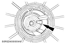
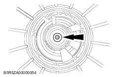
CAUTION:The center support nut could fall into the remaining assembly if not removed. Remove the screw. | | | -
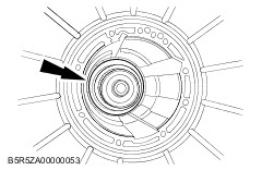
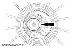
Remove the retaining ring. | | | -
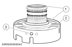
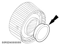
NOTE:The center support is repaired as an assembly. Any damage requires installing a new component. NOTE:When removing the center support, pull evenly around the center support web. Remove the center support. | | | -
Inspect the center support component for wear or damage. - Inspect the thrust surfaces for wear or damage.
- Inspect the center support sealing surface.
- Inspect the fluid passage for blockage or damage.
| | | -
Inspect the seal rings for damage. | | | -
Inspect the bearing for missing rollers or damage. | | | -
Inspect the direct clutch feed hole for blockage or damage. - Rotate the center support bearing to locate the direct clutch feed hole.
- Inspect the direct clutch feed hole for blockage or damage.
| | | -
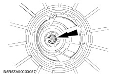
NOTE:Tag and identify the thrust bearing (No.4). Remove the thrust bearing (No.4). | | | -
CAUTION:Failure to loosen the intermediate brake band adjusting screw prior to pump removal may cause damage to the pump and intermediate brake band. CAUTION:Throw the locknut away. The locknut are not reusable for assembly. Remove and discard the locknut, and loosen the intermediate brake band adjusting screw. | | | -
CAUTION:Servo cover is under spring tension. Using the SST, remove the retaining ring and intermediate brake servo cover. | | | -
Remove the intermediate brake servo piston and spring. | | | -
Remove and tag the intermediate brake band anchor strut for assembly. | | | -
CAUTION:Identify the anchor and apply ends of the intermediate brake band. NOTE:The new intermediate brake band is dark in color. This is a normal condition of the band. Hairline cracks in the band are also considered normal. Do not install a new band based solely on the color. Remove and inspect the intermediate brake band. Check the following conditions for installing a new band: - Inspect for missing friction material.
- Inspect for material flaking.
- Inspect for damage to the anchor pins.
| | | -
Remove and tag the intermediate brake band apply strut for assembly. | | | -
NOTE:The thrust bearing (No.5) may come out with the intermediate brake and direct clutch drum. Remove the intermediate brake and direct clutch drum component. | | | -
Remove the thrust bearing (No.5), tag and identify. | | | -
NOTE:The thrust bearing (No.6A) may come out with the cylinder. Tag for reassembly. Remove the forward clutch cylinder. | | | -
NOTE:The thrust bearing (No.6A) may have come out with the forward clutch cylinder. Remove the thrust bearing (No.6A). | | | -
NOTE:The thrust bearing (No.7) may come out with the forward ring gear and hub component. Remove the forward ring gear and hub as an assembly. | | | -
NOTE:The thrust bearing (No.7) may come out with the forward ring gear and hub component. Remove the thrust washer (No. 6B) from the forward ring gear hub. | | | -
Remove the thrust bearing (No.7). | | | -
Remove the forward planetary component. | | | -
Remove the input shell and sun gear component. | | | -
NOTE:Tag and identify the thrust bearing (No.8). Remove the thrust bearing (No.8). | | | -
Remove the retaining ring. | | | -
Remove low/reverse planetary component. | | | -
NOTE:Tag and identify the thrust bearing (No.9). Remove the thrust bearing (No.9). | | | -
NOTE:Use slots located around the outside of the sleeve. Using a small pick, remove the output shaft sleeve. | | | -
WARNING:The output shaft may fall out after removing the retaining ring. Failure to follow these instructions may result in personal injury. CAUTION:Discard the retaining ring. A new retaining ring must be used for assembly. While holding the output shaft, remove and discard the retaining ring. | | | -
Remove the output shaft and park gear. | | | -
NOTE:Tag and identify the thrust washer (No.11). Remove the output shaft thrust washer. | | | -
Remove the output shaft ring gear and hub. | | | -
Remove the thrust bearing (No.10). | | | -
CAUTION:Do not pry on the outer edge of the case or damage to the gasket sealing surface could occur. NOTE:It may be necessary to grind flat spots on the edges of the low/reverse brake band actuating lever shaft in order to remove it. Using a pair of vice grips, hold the flat spots on the low/reverse brake band actuating lever shaft, wiggle it back and forth and remove the low/ reverse brake band actuating lever shaft. | | | -
Remove the low/reverse brake band actuating lever component. | | | -
NOTE:The inner race of the rear one-way clutch is not removable. It is repaired in the case. Remove the low/reverse brake drum and one-way clutch component by rotating it clockwise. | | | -
NOTE:The reverse one-way clutch is part of the low/reverse brake drum component. Install a new low/reverse brake drum as an assembly only. Inspect the low/reverse brake drum component and install a new low/reverse brake drum component if damaged. - Inspect the low/reverse brake drum sprags.
- Inspect the low/reverse brake drum rollers.
- Inspect the low/reverse brake drum.
| | | -
Remove the low/reverse brake band. | | | -
CAUTION:To avoid damage, make sure the wrench does not strike the manual valve inner lever pin. Remove the nut. | | | -
Remove the manual shaft retaining pin. | | | -
Disconnect the manual valve inner lever from the parking lever actuating rod. | | | -
Remove the manual valve inner lever. | | | -
Remove the parking lever actuating rod. | | | -
CAUTION:Do not damage the bore. Remove the manual shaft seal. | | |