
Ranger 2WD L4-153 2.5L SOHC VIN C SFI (1998)
4. Raise the vehicle on a hoist and remove the wheels. Rotate the driveshaft by turning the axle and measure the runout at the front, the center, and
the rear of the driveshaft with the indicator. If the runout exceeds 0.89 mm (0.035 inch) at the front or center, the driveshaft must be replaced. If
the front and center are within this limit, but the rear runout is not, mark the rear runout high point and proceed to Step 5. If the runout is within the
limits at all points, proceed to Step 7.
5. Scribe alignment marks on the driveshaft and the axle companion flange. Disconnect the driveshaft , rotate it one-half turn, and reconnect it.
Circular axle companion flanges can be turned in one-quarter increments to fine tune the runout condition; half-round axle companion flanges are
limited to two positions. Check the runout at the rear of the driveshaft. If it is still over 0.89 mm. (0.035 inch), mark the high point and proceed to
Step 6. If the runout is no longer excessive, check for vibration at the road test speed. If vibration is still present, re-index the driveshaft slip yoke
on the transmission output shaft one-half turn and road test the vehicle. If the vibration persists, proceed to Step 7.
NOTE: Check the U-joints during re-indexing. If a U-joint feels stiff or gritty, replace the U-joints.
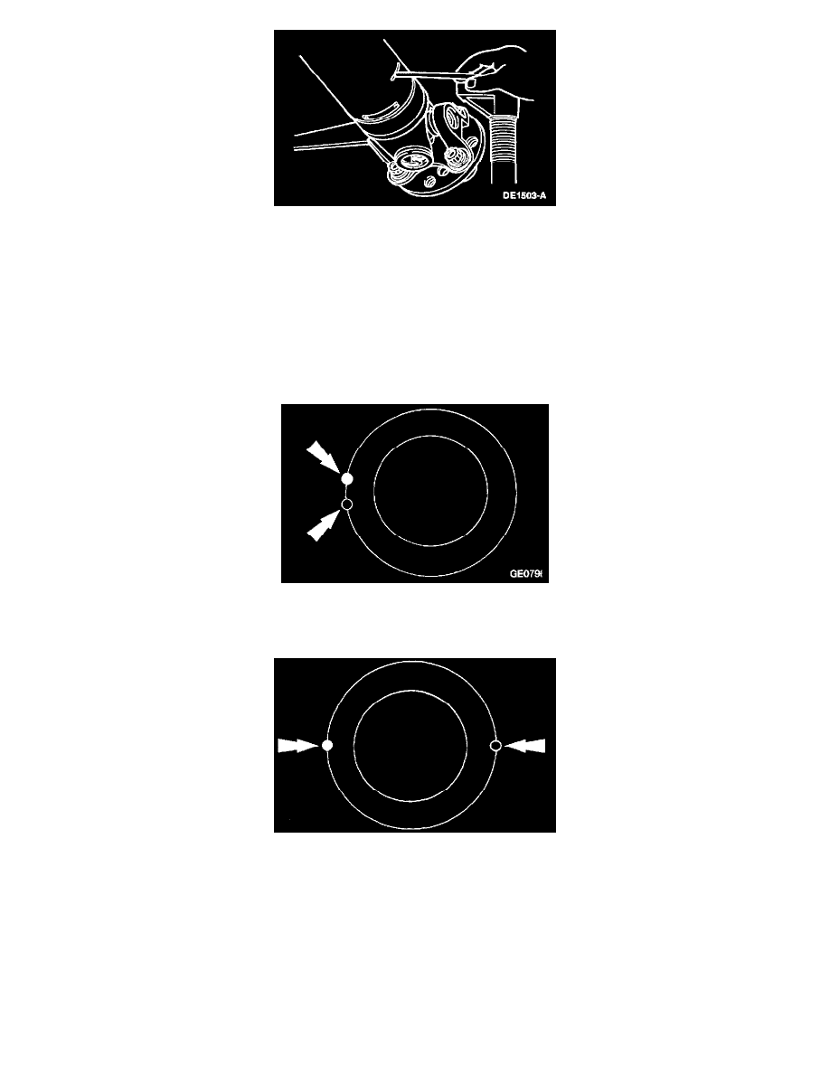
6. Excessive driveshaft runout may originate in the driveshaft itself or in the axle companion flange. To determine which, compare the two high
points marked in Steps 4 and 5. If the marks are close together, within about 25 mm. (1 inch), the shaft must be replaced and the vehicle road
tested.
If the marks are on opposite sides of the driveshaft, the yoke or axle companion flange is responsible for the vibration.
When replacing an axle companion flange, the driveshaft runout must not exceed 0.89 mm (0.035 inch). When runout is within limits, recheck for
vibration at road speed. If vibration persists, balance the driveshaft.
7. To balance the driveshaft, install one or two hose clamps on the driveshaft , near the rear. Position of the hose clamp head(s) can be determined by
trial-and-error.