
Ranger 2WD V6-177 2.9L (1989)
NOTE:
THE HOLE WHERE THE ANTENNA PASSES THROUGH THE COWL IS JUST BELOW THE WINDSHIELD, ABOUT 4" (101.6 MM) FROM
THE RIGHT SIDE. IT IS ONLY NECESSARY TO GAIN ACCESS TO THE HOLE, SO THE INSTRUMENT PANEL DOES NOT HAVE TO BE
TOTALLY REMOVED FROM THE VEHICLE.
7.
Replace the antenna cable with a one-piece cable provided in Service Kit (E3TZ-18813-B).
a.
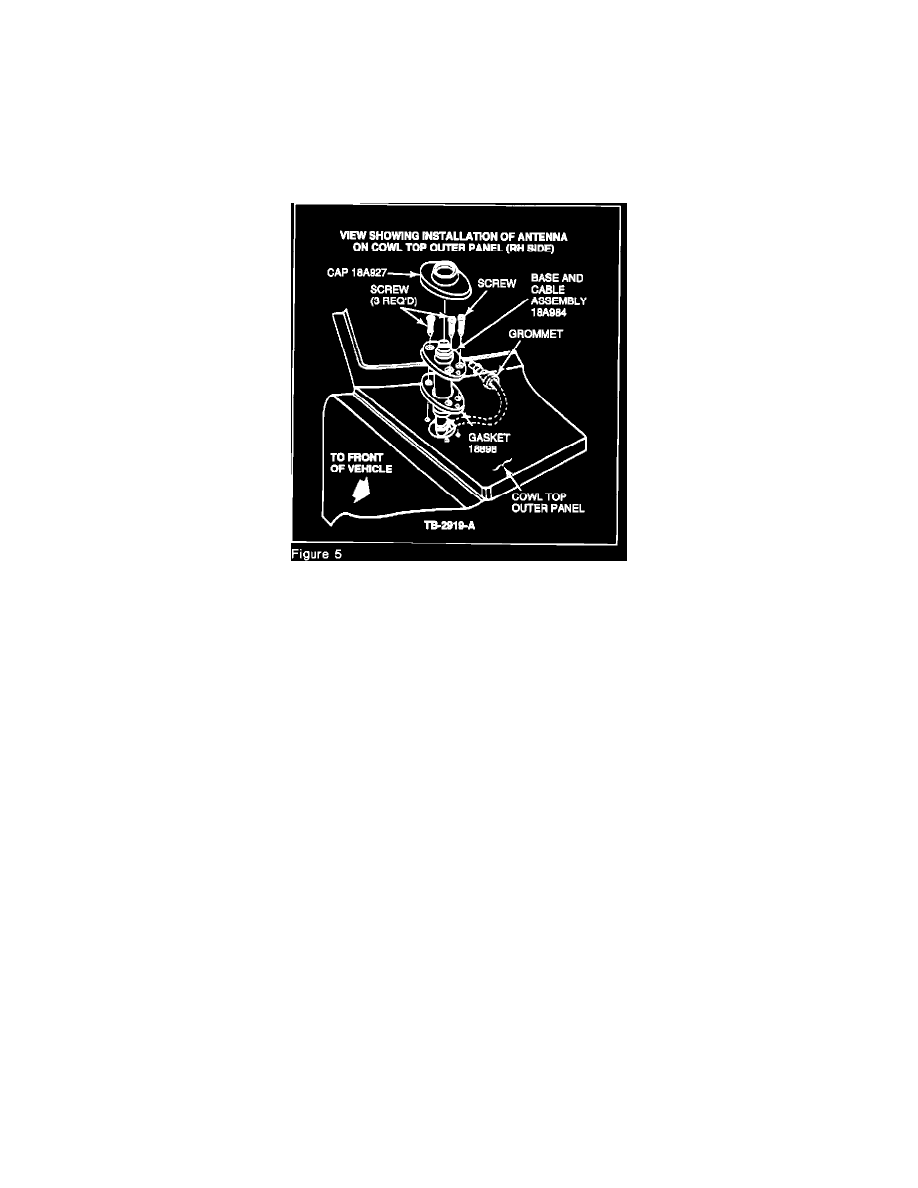
Route the new antenna cable through the fender and cowl hole.
b.
Seat the grommet. See Figure 5 for details.
8.
Route the new cable in the instrument panel along the same path as the original to the radio opening.
CAUTION:
DO NOT POSITION THE CABLE USING THE RETAINERS INCLUDED WITH THE ANTENNA KIT AS SHOWN IN THE ACCOMPANYING
INSTRUCTION SHEET IS-5082-B.
9.
Reinstall the instrument panel.
10.
Reinstall the radio.
11.
Install the antenna base on the cowl top outer panel per service Manual.
NOTE:
THE KIT INCLUDES A NEW MAST AND BASE COVER. USING THE NEW WHIP MAY CAUSE INCREASED WIND NOISE. THEREFORE,
ITS USE IS NOT RECOMMENDED. THE BASE COVERS DIFFER ONLY IN COLOR, AND MAY BE INTERCHANGED IF THE CUSTOMER
WISHES TO DO SO.
1990 CROWN VICTORIA/GRAND MARQUIS
1.
Replace the existing antenna system with instrument panel cable (F1VY-18812-D).
2.
Replace the antenna using the following components.
^
Power Antenna: F0AZ-18850-A
^
Fixed Antenna: F0AZ-18A984-A
3.
Use the replace procedure outlined in the 1990 Crown Victoria/Grand Marquis Service Manual, Sections 35-10 or 15-02.
PART NUMBER
PART NAME
CLASS