
Ranger 2WD V6-245 4.0L VIN X SFI (1997)
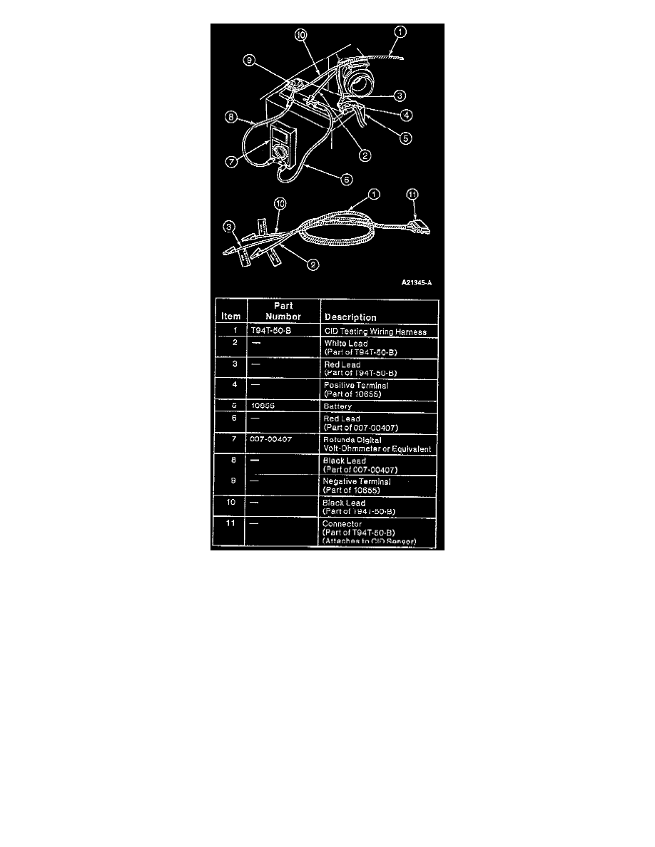
20. Connect the CID Testing Wiring Harness leads:
a. Red harness wire to battery positive terminal.
b. Black harness wire to battery negative terminal.
c. Voltmeter positive lead to harnesses white lead.
d. Voltmeter negative lead to battery negative terminal.
21. Rotate engine two revolutions to take up slack in timing chain and return No. 1 cylinder to its compression stroke.
22. Verify that No. 1 cylinder is on its compression stroke (both valves closed).
NOTE: No. 1 cylinder must be at 26 degrees After Top Dead Center (ATDC) to set CID sensor.
23. Continue to rotate the crankshaft until the new 26 degrees ATDC mark lines up with the timing pointer.
24. While rotating the CID sensor, note the exact point where the sensor switches from 0 to 12 volts on the voltmeter.
NOTE: The voltmeter will register battery voltage whenever the CID sensor closes and makes a complete circuit.
25. Rotate the CID sensor clockwise past the CID switching point (from 12 to 0 volts).
NOTE: The final movement to set the CID sensor must be in a COUNTERCLOCKWISE direction.
26. Rotate the CID sensor counterclockwise and stop at the exact point the voltmeter switches from 0 to 12 volts.