
Ranger 2WD V6-3.0L (2008)
Part 2
Removal
WARNING:
-
Always carry or place a live air bag module with the air bag and deployment door/trim cover/tear seam pointed away from the body. Do
not set a live air bag module down with the deployment door/trim cover/tear seam face down. Failure to follow these instructions may
result in serious personal injury in the event of an accidental deployment.
-
Never probe the electrical connectors on air bag, safety canopy or side air curtain modules. Failure to follow this instruction may result in
the accidental deployment of these modules, which increases the risk of serious personal injury or death.
-
Do not repaint air bag modules with discolored or damaged trim covers or deployment doors; new air bag modules must be installed.
Failure to follow this instruction may result in the air bag deploying incorrectly, which increases the risk of serious personal injury or
death in a crash.
NOTE:
-
The air bag warning indicator illuminates when the restraints control module (RCM) fuse is removed and the ignition switch is ON. This is normal
operation and does not indicate a supplemental restraint system (SRS) fault.
-
The SRS must be fully operational and free of faults before releasing the vehicle to the customer.
-
A repair is made by installing a new part only. If the new part does not correct the condition, install the original part and perform the diagnostic
procedure again.
1. Remove the driver air bag module.
2. NOTE: Make sure the wheels are in the straight-ahead position.
Remove the steering wheel.
3. Remove the ignition lock cylinder.
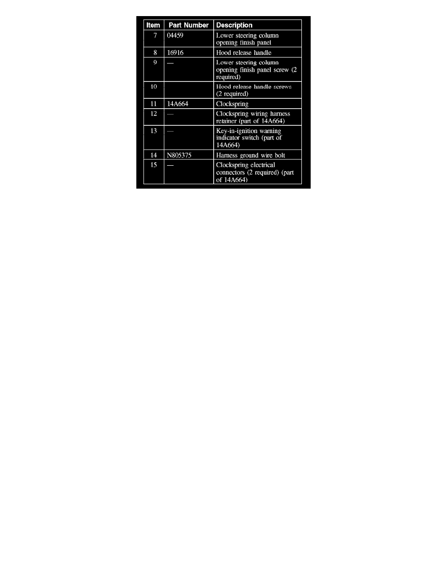
4. Remove the 2 screws and position the hood release handle aside.
5. Remove the 2 screws from the lower steering column opening finish panel. Then pull out to release the retaining clips and remove the lower
steering column opening finish panel.
6. Remove the 5 bolts and lower steering column opening finish panel reinforcement.
7. If equipped, remove the tilt wheel handle and shank.
8. Remove the 3 screws and lower steering column shroud.
9. Position the upper steering column shroud up enough to access the clockspring retaining clips.
10. Detach the clockspring wire harness from the wiring retainer.
11. Disconnect the clockspring electrical connectors.
-
Disconnect the harness ground wire.
-
Release the pin-type retainers and disconnect the clockspring electrical connectors.