
Ranger 2WD V6-4.0L (2010)
Removal and Installation
WARNING: Do not use any fluid other than clean brake fluid meeting manufacturer's specification. Additionally, do not use brake fluid that
has been previously drained. Following these instructions will help prevent system contamination, brake component damage and the risk of
serious personal injury.
WARNING: Carefully read cautionary information on product label. For EMERGENCY MEDICAL INFORMATION seek medical advice. In
the USA or Canada on Ford/Motorcraft products call: 1-800-959-3673. For additional information, consult the product Material Safety Data
Sheet (MSDS) if available. Failure to follow these instructions may result in serious personal injury.
NOTICE: Do not spill brake fluid on painted or plastic surfaces or damage to the surface may occur. If brake fluid is spilled onto a painted or
plastic surface, immediately wash the surface with water.
1. NOTE: This step is only necessary if a new ABS module is being installed.
Connect the scan tool and upload the module configuration information from the ABS module.
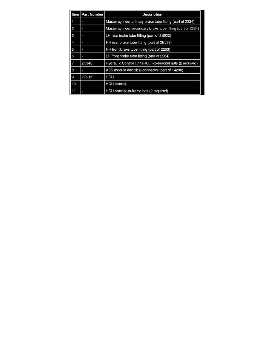
2. Disconnect the ABS module electrical connector by rotating the release lever.
3. NOTE: After disconnecting the Hydraulic Control Unit (HCU) brake tube fittings, cap the holes in the HCU to prevent contamination or foreign
material from entering the brake tube ports.
Disconnect the 6 HCU brake tube fittings from the HCU.
-
To install, tighten the master cylinder primary brake tube fitting to 25 Nm (18 lb-ft).
-
To install, tighten the remaining brake tube fittings to 18 Nm (159 lb-in).
4. Loosen the 2 HCU-to-bracket nuts and remove the HCU assembly.
-
To install, tighten to 8 Nm (71 lb-in).
5. If necessary, remove the 2 HCU bracket-to-frame nuts, the 2 HCU bracket-to-frame bolts and the HCU bracket.
-
To install, tighten to 12 Nm (106 lb-in).
6. To install, reverse the removal procedure.
1. If a new ABS module was installed, download the module configuration. For additional information on configuration, refer to Programmable
Module Installation (PMI) in Information Bus. See: Powertrain Management/Computers and Control Systems/Information Bus/Service and
Repair
2. Bleed the brake system. For additional information, refer to Brakes and Traction Control.