
Ranger 2WD V6-4.0L (2010)
I16 CHECK THE HS-CAN (+) AND HS-CAN (-) CIRCUITS FOR A SHORT TOGETHER WITH THE 4X4 CONTROL MODULE
DISCONNECTED
-
Disconnect: 4X4 Control Module C281a.
-
Measure the resistance between the DLC C251-6, circuit VDB04 (WH/BU), harness side and the DLC C251-14, circuit VDB05 (WH), harness
side.
-
Is the resistance less than 5 ohms?
Yes
GO to I17.
No
CONNECT the negative battery cable. GO to I30.
-------------------------------------------------
I17 CHECK THE HS-CAN (+) AND HS-CAN (-) CIRCUITS FOR A SHORT TOGETHER WITH THE IC DISCONNECTED
-
Disconnect: IC C220b.
-
Measure the resistance between the DLC C251-6, circuit VDB04 (WH/BU), harness side and the DLC C251-14, circuit VDB05 (WH), harness
side.
-
Is the resistance less than 5 ohms?
Yes
REPAIR the circuit. CONNECT all modules. CONNECT the negative battery cable. CLEAR the DTCs. REPEAT the network test with the scan tool.
No
CONNECT the negative battery cable. GO to I31.
-------------------------------------------------
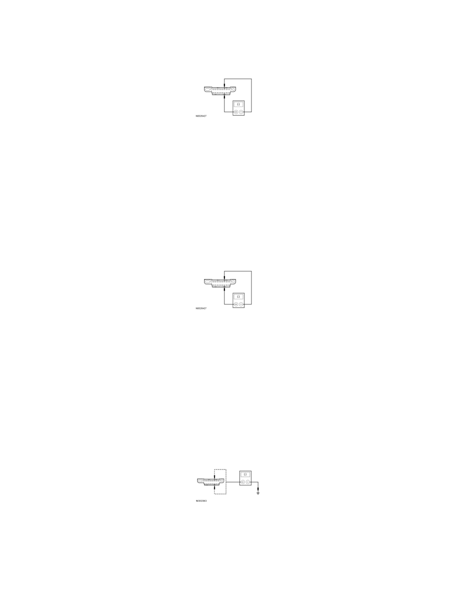
I18 CHECK THE HS-CAN (+) AND HS-CAN (-) CIRCUITS FOR A SHORT TO GROUND WITH THE PCM DISCONNECTED
-
Disconnect: PCM C175b.
-
Measure the resistance between the DLC C251-6, circuit VDB04 (WH/BU), harness side and ground; and between the DLC C251-14, circuit
VDB05 (WH), harness side and ground.
-
Are the resistances greater than 1,000 ohms?
Yes
CONNECT the negative battery cable. GO to I25.
No