
Ranger 2WD V6-4.0L (2010)
CONNECT the negative battery cable. GO to I28.
No
GO to I22.
-------------------------------------------------
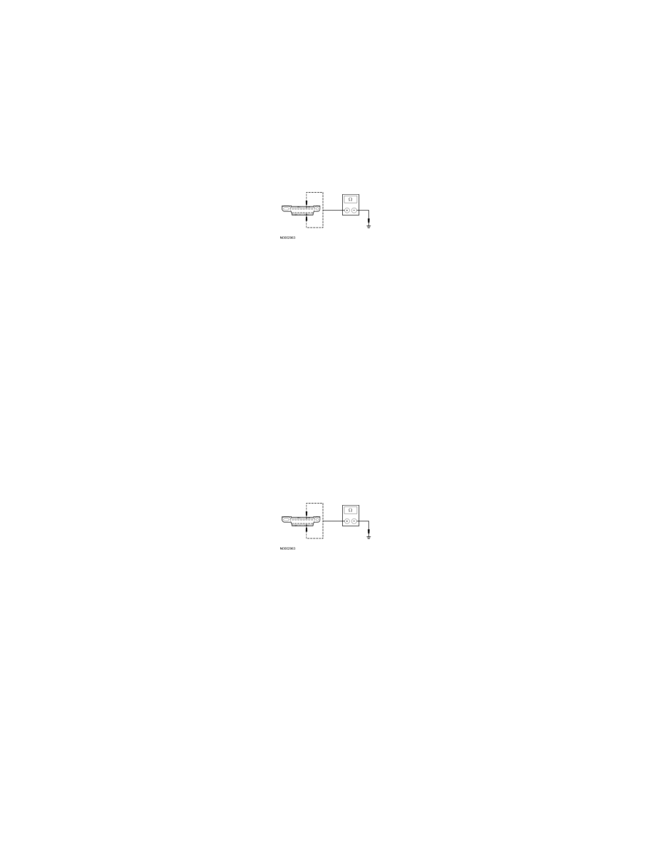
I22 CHECK THE HS-CAN (+) AND HS-CAN (-) CIRCUITS FOR A SHORT TO GROUND WITH THE OCSM DISCONNECTED
-
Disconnect: OCSM C3159.
-
Measure the resistance between the DLC C251-6, circuit VDB04 (WH/BU), harness side and ground; and between the DLC C251-14, circuit
VDB05 (WH), harness side and ground.
-
Are the resistances greater than 1,000 ohms?
Yes
CONNECT the negative battery cable. GO to I29.
No
If the vehicle is equipped with a 4X4 control module, GO to I23.
If the vehicle is not equipped with a 4X4 control module, GO to I24.
-------------------------------------------------
I23 CHECK THE HS-CAN (+) AND HS-CAN (-) CIRCUITS FOR A SHORT TO GROUND WITH THE 4X4 CONTROL MODULE
DISCONNECTED
-
Disconnect: 4X4 Control Module C281a.
-
Measure the resistance between the DLC C251-6, circuit VDB04 (WH/BU), harness side and ground; and between the DLC C251-14, circuit
VDB05 (WH), harness side and ground.
-
Are the resistances greater than 1,000 ohms?
Yes
CONNECT the negative battery cable. GO to I30.
No
GO to I24.
-------------------------------------------------
I24 CHECK THE HS-CAN (+) AND HS-CAN (-) CIRCUITS FOR A SHORT TO GROUND WITH THE IC DISCONNECTED
-
Disconnect: IC C220b.
-
Measure the resistance between the DLC C251-6, circuit VDB04 (WH/BU), harness side and ground; and between the DLC C251-14, circuit
VDB05 (WH), harness side and ground.