| Diagnosis and Testing Refer to Wiring Diagrams Section 413-00, for schematic and connector information. Inspection and Verification - Verify the customer concern.
- Visually inspect for obvious signs of electrical damage.
Visual Inspection Chart | Electrical | | Fuse(s) | | Wiring harness | | Electrical connector(s) | | Light emitting diode(s) LED(s) | | Instrument cluster | | Audio unit | | Climate control assembly | | Switch(es) | | Bulb(s) | - If an obvious cause for an observed or reported concern is found, correct the cause (if possible) before proceeding to the next step.
- If the cause is not visually evident, verify the symptom and refer to the Symptom Chart.
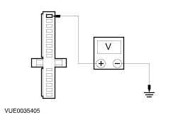
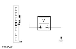
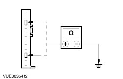
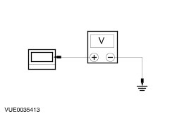
Symptom Chart Symptom Chart | Symptom | Possible Sources | Action | | The Instrument cluster illumination is inoperative | * Circuit(s). * Instrument cluster. | * | | The climate control/integrated control panel illumination is inoperative | * Climate control assembly. * Circuit(s). | * | | The clock illumination is operative | * Clock assembly. * Circuit(s). | * | | The audio unit illumination is inoperative | * Audio unit. * Circuit(s). | * | | The Cigar lighter illumination is inoperative | * Cigar lighter. * Circuit(s). | * | | The Headlamp leveling switch illumination is inoperative | * Headlamp levelling switch. * Circuit(s). | * | Pinpoint Tests | PINPOINT TEST A : THE INSTRUMENT CLUSTER ILLUMINATION IS INOPERATIVE | | TEST CONDITIONS | DETAILS/RESULTS/ACTIONS | | A1: CHECK THE INSTRUMENT CLUSTER FOR POWER | | | 1 Disconnect Instrument Cluster C44. | | | 2 Turn the headlamp switch to the ON position. | | | 3 Measure the voltage between the instrument cluster C44 pin 15, circuit 29S-LA53(OG/BU), harness side and ground. | | | Is the voltage greater than 10 volts? Yes No REPAIR circuit 29S-LA53 (OG/BU). TEST the system for normal operation. | | A2: CHECK THE INSTRUMENT CLUSTER FOR GROUND | | | 1 Measure the resistance between the instrument cluster C44 pin 1, circuit 31-WC43 (BK), harness side and ground. | | | Is the resistance less than 5 ohms? Yes INSTALL a new instrument cluster.
REFER to: Instrument Cluster (413-01 Instrument Cluster, Removal and Installation).
TEST the system for normal operation. No REPAIR circuit 31-WC43 (BK). TEST the system for normal operation. | | PINPOINT TEST B : THE CLIMATE CONTROL/INTEGRATED CONTROL PANEL ILLUMINATION IS INOPERATIVE | | TEST CONDITIONS | DETAILS/RESULTS/ACTIONS | | B1: CHECK CLIMATE CONTROL ASSEMBLY ILLUMINATION FOR POWER | | | 1 Disconnect Climate Control Assembly Illumination C41. | | | 2 Turn the headlamp switch to the ON position. | | | 3 Measure the voltage between the climate control assembly illumination C41 pin 3, circuit 29S-LA28 (OG/YE), harness side and ground. | | | Is the voltage greater than 10 volts? Yes No REPAIR circuit 29S-LA28 (OG/YE). TEST the system for normal operation. | | B2: CHECK CLIMATE CONTROL ASSEMBLY ILLUMINATION FOR GROUND | | | 1 Measure the resistance between climate control assembly illumination C41 pin 2, circuit 91-CA83 (BK/RD), harness side and ground. | | | Is the resistance less than 5 ohms? Yes INSTALL a new climate control assembly.
REFER to: Climate Control Assembly (412-04 Control Components, Removal and Installation).
TEST the system for normal operation. No REPAIR circuit 91-CA83 (BK/RD). TEST the system for normal operation. | | PINPOINT TEST C : THE CLOCK ILLUMINATION IS INOPERATIVE | | TEST CONDITIONS | DETAILS/RESULTS/ACTIONS | | C1: CHECK CLOCK ILLUMINATION FOR POWER | | | 1 Disconnect Clock C67 (vehicles built up to 01/2005). | | | 2 Disconnect Clock C112 (vehicles built 01/2005 onwards). | | | 3 Turn the headlamp switch to the ON position. | | | 4 Measure the voltage between the clock C67 or C112 pin 2, circuit 29S-LA19 (OG/BK), harness side and ground. | | | Is the voltage greater than 10 volts? Yes No REPAIR circuit 29S-LA19 (OG/BK). TEST the system for normal operation. | | C2: CHECK CLOCK ILLUMINATION FOR GROUND | | | 1 Measure the resistance between the clock C67 or C112 pin 3, circuit 31-GB6 (BK), harness side and ground. | | | Is the resistance less than 5 ohms? Yes INSTALL a new clock. TEST the system for normal operation. No REPAIR circuit 31-GB6 (BK). TEST the system for normal operation. | | PINPOINT TEST D : THE AUDIO UNIT ILLUMINATION IS INOPERATIVE | | TEST CONDITIONS | DETAILS/RESULTS/ACTIONS | | D1: CHECK AUDIO UNIT ILLUMINATION FOR POWER | | | 1 Disconnect Audio Unit C7a. | | | 2 Turn the headlamp switch to the ON position. | | | 3 Measure the voltage between the audio unit C7a pin 4, circuit 29S-LA40 (OG/BK), harness side and ground. | | | Is the voltage greater than 10 volts? Yes No REPAIR circuit 29S-LA40 (OG/BK). TEST the system for normal operation. | | D2: CHECK AUDIO UNIT ILLUMINATION FOR GROUND | | | 1 Measure the resistance between the audio unit C7a pin 6, circuit 91-MD15 (BK/GN), and C7a pin2, circuit 91-MD34 (BK/YE harness side and ground. | | | Is the resistance less than 5 ohms? Yes INSTALL a new audio unit.
REFER to: Audio Unit (415-01 Audio Unit, Removal and Installation).
TEST the system for normal operation. No REPAIR circuit 91-MD15 (BK/GN) and 91-MD34 (BK/YE). TEST the system for normal operation. | | PINPOINT TEST E : THE CIGAR LIGHTER ILLUMINATION IS INOPERATIVE | | TEST CONDITIONS | DETAILS/RESULTS/ACTIONS | | E1: CHECK CIGAR LIGHTER ILLUMINATION FOR POWER | | | 1 Disconnect Cigar Lighter C35a. | | | 2 Turn the headlamp switch to the ON position. | | | 3 Measure the voltage between the cigar lighter C35a, circuit 29S-LA18 (OG), harness side and ground. | | | Is the voltage greater than 10 volts? Yes No REPAIR circuit 29S-LA18 (OG). TEST the system for normal operation. | | E2: CHECK THE CIGAR LIGHTER ILLUMINATION FOR GROUND | | | 1 Measure the resistance between the cigar lighter C35b pin 1, circuit 31-HA6 (BK), harness side and ground. | | | Is the resistance less than 5 ohms? Yes INSTALL a new cigar lighter. TEST the system for normal operation. No REPAIR circuit 31-HA6 (BK). TEST the system for normal operation. | | PINPOINT TEST F : THE HEADLAMP LEVELLING SWITCH ILLUMINATION IS INOPERATIVE | | TEST CONDITIONS | DETAILS/RESULTS/ACTIONS | | F1: CHECK THE HEADLAMP LEVELLING SWITCH FOR CORRECT OPERATION | | | 1 Check the headlamp levelling switch for correct operation. | | | Is the headlamp levelling switch operating the headlamps correctly? Yes Install a new headlamp levelling switch. No | | F2: CHECK HEADLAMP LEVELLING SWITCH ILLUMINATION FOR POWER | | | 1 Disconnect Headlamp Levelling Switch C68. | | | 2 Turn the headlamp switch to the ON position. | | | 3 Measure the voltage between the headlamp levelling switch C68 pin 1, circuit 29S-AC9 (OG), harness side and ground. | | | Is the voltage greater than 10 volts? Yes No REPAIR circuit 29S-AC9 (OG). TEST the system for normal operation. | | F3: CHECK HEADLAMP LEVELLING SWITCH ILLUMINATION FOR GROUND | | | 1 Measure the resistance between the headlamp levelling switch C68 pin 4, circuit 31-AC9 (BK), harness side and ground. | | | Is the resistance less than 5 ohms? Yes INSTALL a new headlamp levelling switch. TEST the system for normal operation. No REPAIR circuit 31-AC9 (BK). TEST the system for normal operation. | |