
Taurus V6-182 3.0L DOHC SHO (1992)
Crankshaft Position Sensor: Service and Repair
REMOVAL
1.
Disconnect the battery ground cable.
2.
Remove the accessory drive belts from the engine.
3.
Disconnect the ignition module and remove the intake manifold crossover tube.
4.
Remove the upper timing belt cover.
5.
Disconnect the sensor wiring harness at connector and route wiring harness through belt cover.
6.
Raise vehicle and suitably support.
7.
Remove the right hand wheel assembly.
8.
Using the universal puller (Ford part #T67L-3600-A, or equivalent) remove crankshaft pulley.
9.
Remove center and lower timing belt covers.
10.
Rotate crankshaft BY HAND to position the metal vane of the shutter outside of the sensor air gap.
11.
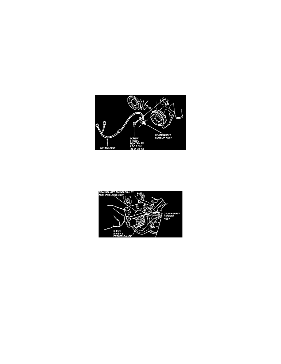
Remove sensor retaining screws and remove sensor.
Crankshaft Timing Sensor
12.
Route sensor wiring harness through the belt cover. Install sensor assembly on mounting pad and install retaining screws. DO NOT tighten the
screws at this time.
INSTALLATION
Adjusting Crankshaft Timing Sensor
1.
Set clearance between crankshaft sensor assembly and one vane on the crankshaft timing pulley and vane assembly using an 0.03 in (0.8 mm)
feeler gauge. Tighten the sensor retaining screws to 22-31 lb in (2.5-3.5 Nm).
CAUTION: This is a critical torque. Overtightening may cause damage to the sensor.
2.
Install lower timing belt cover. Use caution not to damage the sensor wiring harness.
3.
Install crankshaft pulley using crank gear and damper replacer (Ford part #T83T-6316-B2, or equivalent. Tighten pulley bolt to 112-127 ft lb
(152-172 Nm).
4.
Install the center timing belt cover.
5.
Install the right front wheel assembly, torquing the nuts to 85-105 ft lb (115-142 Nm).
6.
Lower vehicle.
7.
Route and connect sensor wiring harness.
8.
Install upper timing belt cover.
9.
Install intake manifold crossover tube and connect ignition module.
10.
Install accessory drive belts and adjust to proper tension.
11.
Connect battery ground cable.