
Taurus V6-182 3.0L DOHC SHO (1992)
Fuel Gauge Sender: Component Tests and General Diagnostics
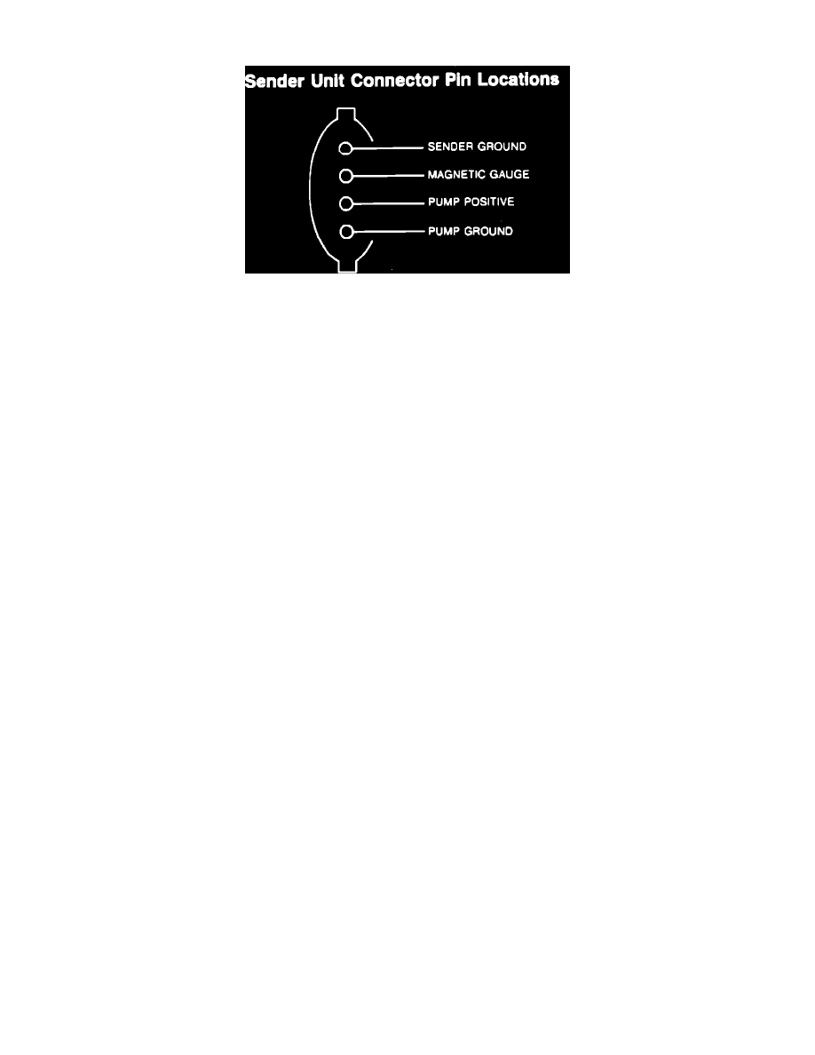
Fuel Sender Connector
Required Test Equipment
^
Rotunda Instrument Gauge System Tester 021-00055 or equivalent
^
a pair of 22 ohm and 145 ohm resistors or another fuel sender of known quality.
Test is Performed With Resistors
1. Disconnect the wiring connector at the sender unit.
2. Connect the resistor between the gauge lead and a suitable ground.
3. turn ignition switch to the ON position.
Results
With the 145 ohm resistor, the gauge pointer should contact the FULL mark at minimum edge of pointer to edge of mark. With the 22 ohm
resistor, the gauge pointer should contact the EMPTY mark (edge of pointer to edge of mark).
Test Performed With Fuel Sender
1. Turn ignition switch to the OFF position.
2. Disconnect the wiring connector from the sender and connect it to the test sender.
3. Move the float rod away from the fuel filter against the FULL stop position (approximately 145 ohms). Wait approximately 30 seconds and turn
ignition switch to the ON position. The gauge should read on or above the FULL mark.
4. Move the float rod toward the fuel filter against the EMPTY stop position (approximately 22 ohms). Turn ignition switch to the OFF position.
Wait approximately 30 seconds and turn ignition to the ON position. The gauge should read on or below the EMPTY mark.
5. If the gauge performs as indicated, perform the fuel sender unit test(s), Pinpoint Test D.
6. If the gauge is out of calibration at the EMPTY mark, or both the EMPTY and FULL mark, replace the gauge.