
Taurus V6-195 3.2L DOHC SHO (1994)
Hall Effect Sensor: Service and Repair
NOTE: Special tool numbers T67L-3600-A and T83T-6316-B2, or equivalent are required for removal and installation of the Crankshaft
Position (CKP) Sensor.
REMOVAL
1. Disconnect battery ground cable.
2. Loosen drive belt tensioner for A/C compressor and power steering pump drive belts.
3. Remove drive belts from crankshaft vibration damper and pulley.
4. Disconnect Ignition Control Module and remove engine air inlet connector.
5. Remove upper outer timing belt cover.
6. Disconnect crankshaft position sensor wiring harness at connector and route crankshaft position sensor wiring harness through outer timing belt
cover.
7. Raise vehicle and suitably support.
8. Remove RH front wheel and tire assembly.
9. Remove crankshaft vibration damper and pulley using Universal Puller (T67L-3600-A).
10. Remove center and lower timing belt cover.
11. Rotate crankshaft by hand to position the metal vane of the crankshaft sprocket outside of crankshaft position sensor air gap.
12. Remove crankshaft position sensor retaining screws and crankshaft position sensor.
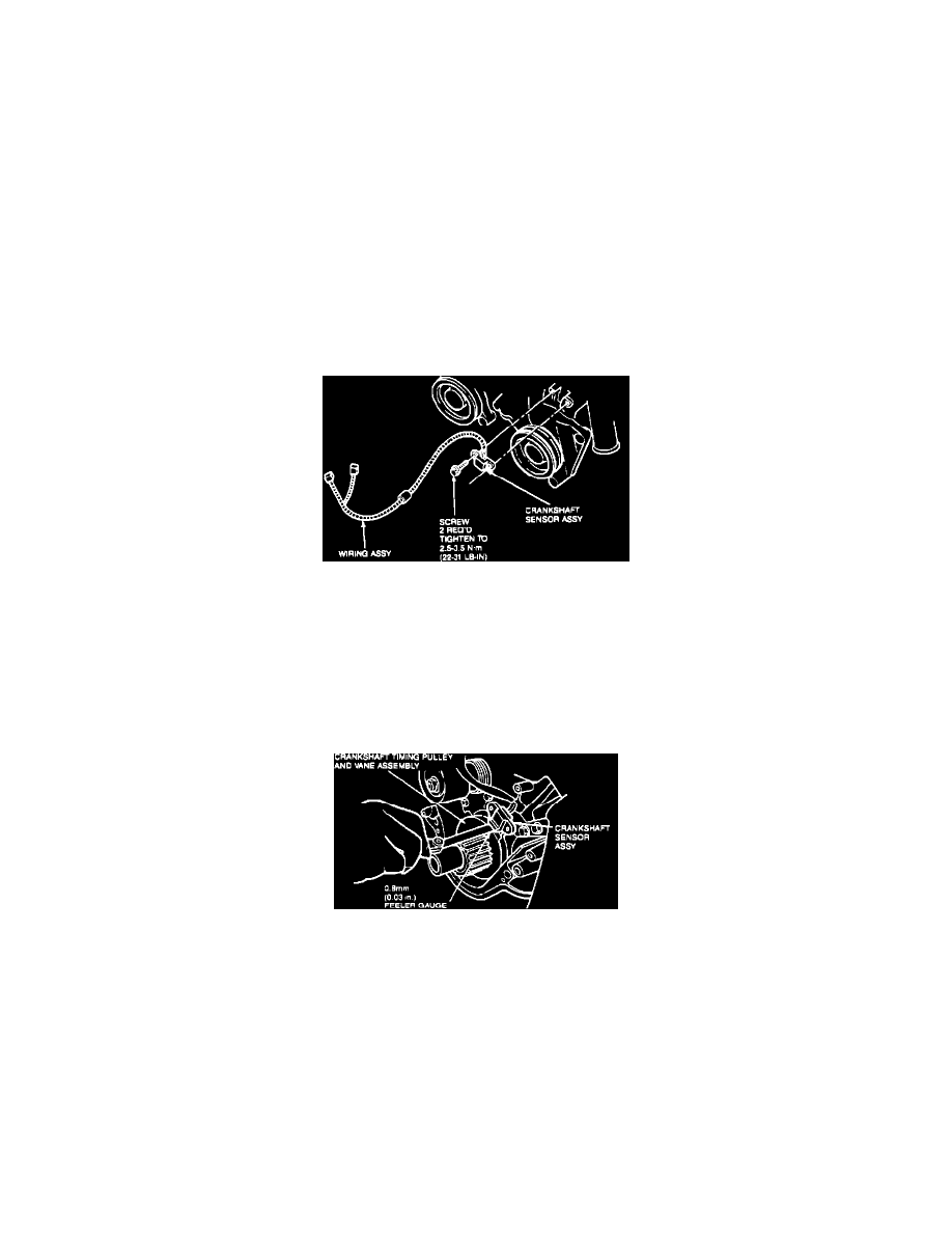
Crankshaft Timing Sensor
INSTALLATION
1. Route crankshaft position sensor wiring harness through outer timing belt cover. Install crankshaft position sensor on mounting pad and install
retaining screws loosely. Do not tighten screws at this time.
2. Set clearance between crankshaft position sensor assembly and one vane on crankshaft sprocket with a 0.030 inch (0.8 mm) feeler gauge. Tighten
screws to 22-31 In-lbs. (2.5-3.5 Nm).
CAUTION: This is a critical torque. Overtightening can cause damage to the crankshaft position sensor.
Adjusting Crankshaft Timing Sensor
3. Install lower outer timing belt cover. Take care not to damage crankshaft position sensor wiring harness.
4. Install crankshaft vibration damper and pulley using Crank Gear and Damper Replacer (T83T-6316-B2). Tighten pulley bolt to 112-127 ft-lb.
(152-172 Nm).
5. Install center outer timing belt cover.
6. Install RH front wheel and tire. Tighten wheel hub bolt nuts to 85-105 ft-lb. (115-142 Nm).
7. Lower vehicle.
8. Route and connect crankshaft position sensor wiring harness.
9. Install upper outer timing belt cover.
10. Install engine air inlet connector and reconnect Ignition Control Module.
11. Install A/C and power steering drive belts.
12. Reconnect battery ground cable.