
Taurus AWD V6-3.5L (2009)
Yes
GO to Q2.
No
REPAIR the DLC as necessary. CLEAR the DTCs. REPEAT the network test with the scan tool.
-------------------------------------------------
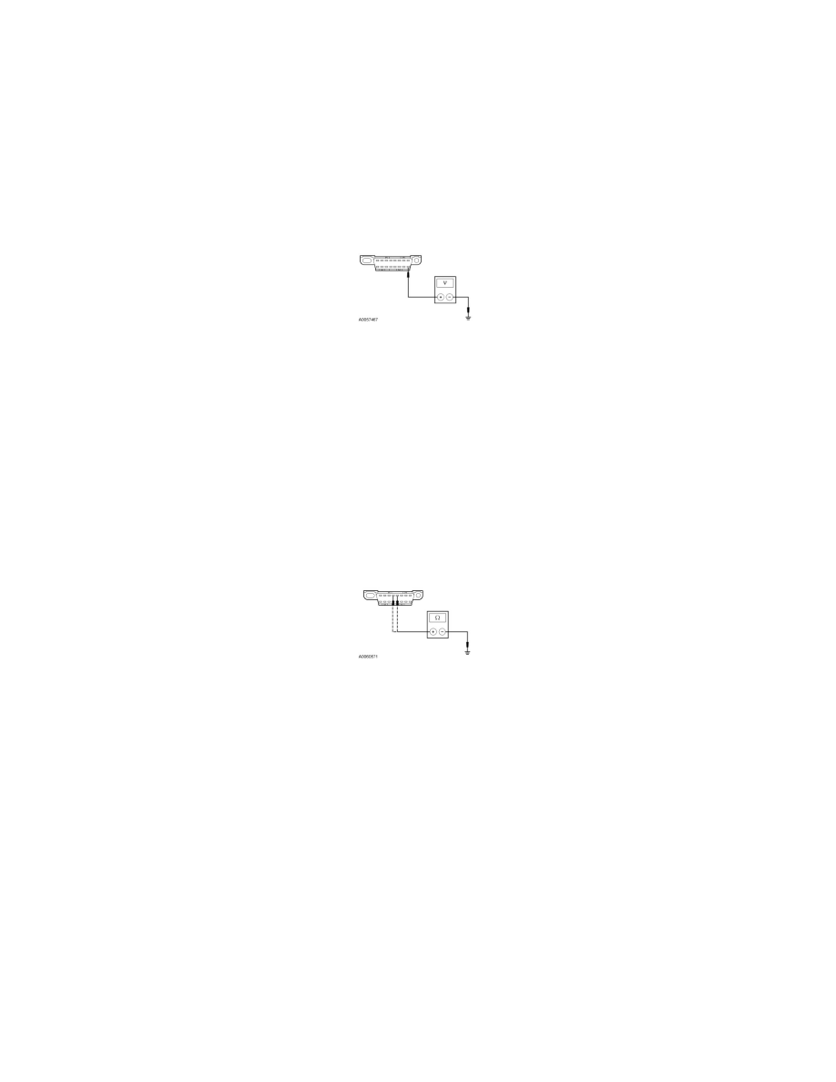
Q2 CHECK THE VOLTAGE SUPPLY CIRCUIT TO THE DLC
-
Measure the voltage between the DLC C251-16, circuit SBP20 (GN/RD), harness side and ground.
-
Is the voltage greater than 10 volts?
Yes
GO to Q3.
No
VERIFY the Smart Junction Box (SJB) fuse 20 (15A) is OK. If OK, REPAIR the circuit. If not OK, Refer to the Wiring Diagrams to identify the
possible causes of the short circuit. REPEAT the network test with the scan tool.
-------------------------------------------------
Q3 CHECK THE DLC GROUND CIRCUITS FOR AN OPEN
-
Measure the resistance between the DLC C251-4 and C251-5, circuits GD111 (BK/BU), harness side and ground.
-
Are the resistances less than 5 ohms?
Yes
REPAIR the scan tool. REPEAT the network test with the scan tool.
No
REPAIR the circuit in question. REPEAT the network test with the scan tool.
-------------------------------------------------
Pinpoint Test R: Intermittent No High Speed Controller Area Network (HS-CAN) Communication,
Communication Can Be Intermittently
Communications Network
Pinpoint Tests
Pinpoint Test R: Intermittent No High Speed Controller Area Network (HS-CAN) Communication, Communication Can Be Intermittently
Established
Normal Operation