| Installation Special Tool(s) | | Spacer, Subframe 204-606 | | | Worldwide Diagnostic System (WDS) 418-F224 | General Equipment M8 x 45 mm bolt Transmission jack 12 mm drill bit Materials Name Specification Grease ESD-M2C220-A Plug E852068 Installation All vehicles | | -
Check the pilot bearing for damage. If damaged, install a new pilot bearing.
For additional information, refer to: Pilot Bearing (308-01A Clutch - Vehicles With: MT-75, Removal and Installation).
| | | -
NOTE:Do not apply grease to a newly installed pilot bearing. Apply approximately one gram of grease to the pilot bearing. | | | -
Apply a thin film of grease to the input shaft guide sleeve. | | | -
CAUTION:Do not tilt the transmission during installation. This may cause damage to the pilot bearing. | | | -
NOTE:Do not fully tighten the transmission retaining bolts at this stage. Install one transmission retaining bolt to the right-hand side and one to the left-hand side. | | | -
Remove the locating studs. | | | -
Install the remaining transmission retaining bolts to the right-hand side. | | | -
Install the remaining transmission retaining bolts to the left-hand side. | | | -
Remove the dust cap and, using a suitable M8 x 45 mm bolt, shift the gearshift actuator rod into the neutral position. | | | -
Shift the transmission into neutral. | | | -
Apply grease to the gearshift shaft connector. | | | -
CAUTION:Make sure that the gearshift actuator ball joint slides into the gearshift shaft connector bore. Install the gearshift actuator. - Tighten the bolts in the sequence shown.
| | | -
Install the gearshift actuator shift cover. - Secure with the two clips.
| | | -
Using a 12 mm drill bit, drill a hole into the transmission housing (as shown). | | | -
CAUTION:Make sure that the clutch actuator rod correctly engages with the clutch release lever. Attach the clutch actuator to the transmission. - Use the hole in the transmission housing to check the engagement of the clutch actuator rod.
| | | -
Install a plug to close off the hole in the transmission housing. | | | -
Connect the crankshaft position (CKP) sensor electrical connector and attach the heat shield. | | | -
Connect the vehicle speed sensor (VSS) electrical connector. | | | -
Connect the input shaft speed (ISS) sensor electrical connector. | | | -
Connect the reversing lamp switch electrical connector. | Vehicles with tachograph | | -
NOTE:Vehicles built up to 10/2001 have a four bolt transmission output flange. Vehicles built 10/2001 onwards have a three bolt transmission output flange. Connect the tachograph sensor electrical connector. | All vehicles | | -
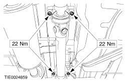
Raise the front axle crossmember and tighten the four retaining bolts (left-hand side shown). | | | -
Remove the transmission jack from under the front axle crossmember. | | | -
NOTE:When using a two post lift. Remove the wooden block. | | | -
NOTE:When using a four post lift. Remove the transmission jack from under the engine crossmember. | | | -
Install the transmission support insulator to front axle crossmember bolts. | | | -
Attach the power steering lines to the front axle crossmember. | | | -
WARNING:Install a new steering column flexible coupling lower nut and bolt. Failure to follow this instruction may result in personal injury. NOTE:Make sure that the circlip is correctly seated. Connect the steering column flexible coupling to the steering gear pinion. | | | -
Install the new driveshaft center bearing retaining bolts. | Vehicles built up to 10/2001 | | -
NOTE:Align the mark on the driveshaft flange with the mark on the transmission output shaft flange. NOTE:Use new driveshaft to transmission output shaft flange bolts. Attach the driveshaft to the transmission output shaft flange. | Vehicles built 10/2001 onwards | | -
NOTE:Align the mark on the driveshaft flange in relation to the transmission output shaft flange. NOTE:Use new driveshaft to transmission output shaft flange bolts. Attach the driveshaft to the transmission output shaft flange. | All vehicles | | -
Connect the battery ground cable.
For additional information, refer to: Battery Disconnect and Connect (414-01 Battery, Mounting and Cables, General Procedures).
| | | -
Using worldwide diagnostic system (WDS), allow the transmission control module to relearn the clutch parameters. | | | -
Check the front toe adjustment, adjust if necessary.
For additional information, refer to: Specifications (204-00 Suspension System - General Information, Specifications).
| |