| Disassembly Special Tool(s) | | Remover, Drive Pinion Oil Seal 205-078 (15-048) | | | Adapter for 205–078 (Thrust Pad) 205-078-01 (15-048-01) | | | Remover, Differential Bearing Cone 205-176 (15-074) | | | Mounting Bracket, Engine/Differential 205-329 (15-105A) | | | Mounting Stand 303-435 (21-187) | | | Mounting Bracket for 303-435 303-435-06 (21-031B) | | | Remover, Halfshaft Oil Seal 308-208 (16-074) | General Equipment Two tyre levers Hardwood drift Disassembly | | -
Mount the transaxle on the mounting stand. | | | -
Remove the gearshift cable retaining bracket. | | | -
NOTE:Ensure that the selector mechanism is in the neutral position. Remove the selector mechanism. | | | -
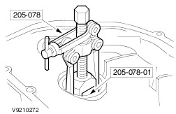
NOTE:Discard the oil seal. Using the special tool, remove the halfshaft oil seals (left-hand side shown). | | | -
Remove the vehicle speed sensor (VSS) (if equipped). | | | -
Clean any grease and foreign material from the input shaft. | | | -
CAUTION:If brake fluid is spilt on the paintwork, the affected area must be immediately washed down with cold water. CAUTION:Using suitable adhesive tape, cover the input shaft splines to prevent damage to the input shaft oil seal. NOTE:Check the clutch slave cylinder assembly for fluid leaks or damage. Install new parts as necessary. Remove the clutch slave cylinder assembly. | | | -
Remove the adhesive tape from the input shaft splines. | | | -
NOTE:Do not remove the dowel pins. Remove the transaxle housing retaining bolts (19 bolts and 2 studs). | | | -
Remove the differential assembly. - Remove the magnetic disc.
| | | -
Remove the reverse gear idler shaft retaining bolts. | | | -
Remove the selector rods. | | | -
Remove the selector forks. - Remove the first and second gear selector fork.
- Remove the third and fourth gear selector fork.
- Remove the fifth and reverse gear selector fork.
| | | -
Remove the reverse gear idler shaft mounting bracket. - Move the input shaft and output shaft to the side (the reverse gear idler shaft mounting bracket should lift up).
- Remove the reverse gear idler shaft mounting bracket.
| | | -
Remove the input shaft and the output shaft. | | | -
Remove the reverse gear idler with the needle roller bearing and the thrust washers. | | | -
NOTE:Locate the special tool in the housing recesses. Using the special tool, remove the differential bearing cup. | | | -
NOTE:Locate the special tool in the housing recesses. Using the special tool, remove the input shaft and output shaft bearing cups. | | | -
NOTE:Locate the special tool in the housing recesses. Using the special tool, remove the bearing cups and the adjustment shim from the differential and from the input shaft. | | | -
NOTE:Locate the special tool in the housing recesses. Using the special tool, remove the output shaft bearing cup and the adjusting shim. | | | -
CAUTION:Only remove the reverse gear idler shaft if it is damaged. Remove the reverse gear idler shaft retaining bolts. | | |