| PINPOINT TEST B : THE HORN DOES NOT SOUND |
| TEST CONDITIONS | DETAILS/RESULTS/ACTIONS |
| B1: CHECK THE POWER TO THE HORN RELAY |
| | 1 Measure the voltage between the horn relay C1006 pin 2, circuit 30-GJ6A (RD), harness side and ground; and between C1006 pin 5, circuit 30-GJ6 (RD), harness side and ground. |
| | Are the voltages greater than 10 volts? Yes No If fuse 7 is OK, REPAIR the power feed to the horn relay, circuit 30-GJ6A (RD) or circuit 30-GJ6 (RD). If fuse 7 has failed, INSTALL a new fuse. TEST the system for normal operation. If the fuse fails again, REPAIR the power feed to the horn relay, circuit 30-GJ6A (RD) or circuit 30-GJ6 (RD). TEST the system for normal operation. |
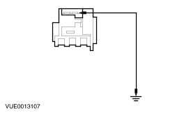
| B2: CHECK THE HORN CIRCUIT |
| | 1 Measure the resistance between the horn relay C1006 pin 3, circuit 30S-GJ6 (RD/YE), harness side and ground. |
| | Is the resistance between 0.5 and 4.0 ohms? Yes No REPAIR circuit 30S-GJ6 (RD/YE). TEST the system for normal operation. |
| B3: CHECK THE STEERING WHEEL HORN SWITCH |
WARNING:To deactivate the air bag, refer to the procedure in Section 501-20B for the correct air bag deactivation procedure. Failure to follow this instruction, may result in personal injury. |
| | 1 |
| | 2 Disconnect Horn Switch N54. |
| | 3 Measure the resistance between the horn switch connectors (component side). |
| | Is the resistance less than 0.5 ohms with the horn switch pressed and greater than 10,000 ohms with the horn switch released? Yes No INSTALL a new horn switch. TEST the system for normal operation. |
| B4: CHECK THE HORN SWITCH POSITIVE FEED CIRCUIT |
| | 1 Connect Horn Relay C1006. |
| | 2 Measure the voltage between the horn switch power feed circuit 31S-GJ6 (GN/BK) and ground. |
| | Is the voltage greater than 10 volts? Yes No |
| B5: CHECK THE HORN SWITCH GROUND CIRCUIT |
| | 1 Disconnect Air Bag Sliding Contact C281b. |
| | 2 Measure the resistance between the horn switch ground circuit 31-GJ6 (GN) and the air bag sliding contact C218b pin 1. |
| | Is the resistance less than 0.5 volts? Yes REPAIR circuit 31-GJ6 (BK). TEST the system for normal operation. No INSTALL a new air bag sliding contact. TEST the system for normal operation. |
| B6: CHECK THE HORN SWITCH POSITIVE FEED CIRCUIT |
| | 1 Disconnect Air Bag Sliding Contact C281b. |
| | 2 Measure the resistance between the horn switch power feed circuit 31S-GJ6 (GN/BK) and the air bag sliding contact C218b pin 2. |
| | Is the resistance less than 0.5 volts? Yes REPAIR circuit 31S-GJ6 (BK/YE). TEST the system for normal operation. No INSTALL a new air bag sliding contact. TEST the system for normal operation. |