| Diagnosis and Testing Refer to Wiring Diagrams Section 414-02, for schematic and connector information. Surface charge dissipation unit (SCD²) Micro390 battery tester Principles of Operation: All except vehicles with 2.4L diesel engine The generator, generates alternating current (AC) which is internally converted to direct current (DC). This current is supplied to the vehicle electrical system through the output (B+) terminal of the generator. With the engine running, voltage is applied through the warning indicator, circuit 8-BA9 (WH/GN) to the voltage regulator. This turns the regulator on, allowing current to flow from the battery circuit 30-BA12 (RD) to the generator field coil. When the generator begins generating current, a voltage signal is taken from the generator stator and fed back to the regulator internally. This voltage feedback signal (typically half the battery voltage) is used to turn off the warning indicator. Principles of Operation: Vehicles with 2.4L diesel engine Vehicles equipped with a 2.4L diesel engine are fitted with a generator cut-off relay. The relay will make sure that the voltage feedback signal is only applied to the instrument cluster and central junction box (CJB) when the ignition is in the ON position. As soon as the ignition is switched to the OFF position, the generator cut-off relay grounds the instrument cluster isolating the charging system warning indicator. Inspection and Verification WARNING:Batteries contain sulphuric acid. Avoid contact with skin, eyes, or clothing. Also, shield your eyes when working near batteries to protect against possible splashing of the acid solution. In case of acid contact with skin or eyes, flush immediately with water for a minimum of 15 minutes and get prompt medical attention. If acid is swallowed, call a physician immediately. Failure to follow these instructions may result in personal injury. WARNING:Batteries normally produce explosive gases which can cause personal injury. Therefore, do not allow flames, sparks or lighted substances to come near the battery. When charging or working near a battery, always shield your face and protect your eyes. Always provide ventilation. Failure to follow these instructions may result in personal injury. - Verify the customer concern.
- Visually inspect for obvious signs of mechanical or electrical damage.
Visual Inspection Chart | Mechanical | Electrical | - Accessory drive belt
- Generator
- Generator decoupler
| - Fuse(s)
- Wiring harness
- Battery junction box (BJB)
- CJB
- Battery
- Battery cable(s)
- Charging system warning indicator
- Relay(s)
| - If an obvious cause for an observed or reported concern is found, correct the cause (if possible) before proceeding to the next step.
- Check the operation of the charging system warning indicator lamp, located in the instrument cluster. Normal operation is as follows:
Normal Charging System Voltages | Ignition Switch Position | A Circuit 30-BA12 (RD) | I Circuit 8-BA9 (WH/GN) | Generator B+ Circuit 30-BA6 (RD) | Battery | Engine to battery ground | Charging System Warning Indicator Operation | | OFF | 12V | 0V | 12V | 12V | 0V | OFF | | RUN-engine off | 12V | 1-3V | 12V | 12V | 0V | Illuminated | | RUN-engine running | 13-15V | 13-15V | 13-15V | 13-15V | 0V | OFF | - If the cause is not visually evident, verify the symptom and refer to the Symptom Chart.
Symptom Chart | Symptom | Possible Sources | Action | | The battery is discharged or battery voltage is low | * High current drain(s). * Battery. | * CARRY OUT the battery test, REFER to the Battery Test in Component Tests in this section. | | * Generator. | * CARRY OUT the generator tests, REFER to the Generator On-Vehicle Tests in Component Tests in this section. | | The charging system warning indicator is on with the engine running (The battery voltage does not increase) | * Accessory drive belt. | * CHECK the accessory drive belt condition,
REFER to: Accessory Drive (303-05 Accessory Drive, Diagnosis and Testing).
| | * Generator decoupler (vehicles with 2.4L diesel engine). | * CARRY out the Generator Decoupler Component Test. | | * Generator. | * CARRY OUT the generator tests, REFER to the Generator On-Vehicle Tests in Component Tests in this section. | | * Circuit. * Generator cut-off relay (vehicles with 2.4L diesel engine). | * | | The System Overcharges (Battery Voltage is Greater than 15.5 Volts) | * Circuit. | * | | * Generator. | * CARRY OUT the generator tests, REFER to the Generator On-Vehicle Tests in Component Tests in this section. | | The Charging System Warning Indicator is ON with the Engine Running and the Battery Increases Voltage | * Generator. | * CARRY OUT the Generator Component Tests in this section. | | * Instrument cluster. | * Vehicles built up to 07/2003,
REFER to: Instrument Cluster - Vehicles Built Up To: 07/2003, Vehicles With: Central Junction Box (CJB) (413-01 Instrument Cluster, Diagnosis and Testing).
Vehicles built from 07/2003,
REFER to: Instrument Cluster - Vehicles Built From: 07/2003, Vehicles With: Central Junction Box (CJB) (413-01 Instrument Cluster, Diagnosis and Testing).
| | * Powertrain control module (PCM). | * REFER to the WDS. | | * Circuit. | * | | The Charging System Warning Indicator is OFF with the Ignition Switch in the RUN Position and the Engine Off (Battery Voltage does not increase) All except vehicles with 2.4L diesel engine built up to 07/2003 | * Circuit. | * | | * Battery. | * CARRY OUT the battery test, REFER to the Battery Test in Component Tests in this section. | | * Instrument cluster. | * Vehicles built up to 07/2003,
REFER to: Instrument Cluster - Vehicles Built Up To: 07/2003, Vehicles With: Central Junction Box (CJB) (413-01 Instrument Cluster, Diagnosis and Testing).
| | * Powertrain control module (PCM). | * REFER to the WDS. | | The Charging System Warning Indicator is OFF with the Ignition Switch in the RUN Position and the Engine Off (Battery Voltage does not increase) All except vehicles with 2.4L diesel engine built 07/2003 onwards | * Circuit. | * | | * Battery. | * CARRY OUT the battery test, REFER to the Battery Test in Component Tests in this section. | | * Instrument cluster. | * Vehicles built up to 07/2003,
REFER to: Instrument Cluster - Vehicles Built Up To: 07/2003, Vehicles With: Central Junction Box (CJB) (413-01 Instrument Cluster, Diagnosis and Testing).
Vehicles built from 07/2003,
REFER to: Instrument Cluster - Vehicles Built From: 07/2003, Vehicles With: Central Junction Box (CJB) (413-01 Instrument Cluster, Diagnosis and Testing).
| | * Powertrain control module (PCM). | * REFER to the WDS. | | The Charging System Warning Indicator is OFF with the Ignition Switch in the RUN Position and the Engine Off (Battery Voltage does not increase) Vehicles with 2.4L diesel engine built up to 07/2003 | * Circuit. * Generator cut-off relay | * | | * Battery. | * CARRY OUT the battery test, REFER to the Battery Test in Component Tests in this section. | | * Instrument cluster. | * Vehicles built up to 07/2003,
REFER to: Instrument Cluster - Vehicles Built Up To: 07/2003, Vehicles With: Central Junction Box (CJB) (413-01 Instrument Cluster, Diagnosis and Testing).
Test the system for normal operation. | | * Powertrain control module (PCM). | * REFER to the WDS. | | The Charging System Warning Indicator is OFF with the Ignition Switch in the RUN Position and the Engine Off (Battery Voltage does not increase) Vehicles with 2.4L diesel engine built 07/2003 onwards | * Circuit. * Generator cut-off relay | * | | * Battery. | * CARRY OUT the battery test, REFER to the Battery Test in Component Tests in this section. | | * Instrument cluster. | * Vehicles built 07/2003 onwards,
REFER to: Instrument Cluster - Vehicles Built From: 07/2003, Vehicles With: Central Junction Box (CJB) (413-01 Instrument Cluster, Diagnosis and Testing).
Test the system for normal operation. | | * Powertrain control module (PCM). | * REFER to the WDS. | | The Charging System Warning Indicator Flickers or is Intermittent | * Circuit. | * | | * Generator. | * CARRY OUT the generator tests, REFER to the Generator On-Vehicle Tests in Component Tests in this section. | | The Generator is Noisy Vehicles built up to 07/2003 | * Generator. | * | | * Generator decoupler (vehicles with 2.4L diesel engine). | * CARRY out the Generator Decoupler Component Test. | | * Loose generator mounting bolts. | * TIGHTEN the generator mounting bolts. | | * Accessory drive belt. | * REFER to: Accessory Drive (303-05 Accessory Drive, Diagnosis and Testing). | | The Generator is Noisy Vehicles built 07/2003 Onwards | * Generator. | * | | * Generator decoupler (vehicles with 2.4L diesel engine). | * CARRY out the Generator Decoupler Component Test. | | * Loose generator mounting bolts. | * TIGHTEN the generator mounting bolts. | | * Accessory drive belt. | * REFER to: Accessory Drive (303-05 Accessory Drive, Diagnosis and Testing). | | Radio Interference | * Generator. * Wiring harness routing. * Audio system. | * Vehicles built up to 07/2003, GO to Pinpoint Test K. Vehicles built 07/2003 onwards. GO to Pinpoint Test L. | | Vehicle electrical systems inoperative | * Battery. | * CARRY OUT the battery test, REFER to the Battery Test in Component Tests in this section. | | The engine cranks slowly | * Battery. | * CARRY OUT the battery test, REFER to the Battery Test in Component Tests in this section. | | * Battery cable(s). * Starter motor. | * REFER to: Starting System - Vehicles With: Central Junction Box (CJB) (303-06 Starting System, Diagnosis and Testing) / Starting System - Vehicles Without: Central Junction Box (CJB) (303-06 Starting System, Diagnosis and Testing). | Pinpoint Tests CAUTION:Do not make jumper connections except as directed. Incorrect connections may damage the voltage regulator test terminals, fuses or fuse links. CAUTION:Do not allow any metal object to come in contact with the generator housing and internal diode cooling fins. NOTE:While carrying out any pinpoint test, disregard any DTCs set while following any specific pinpoint test. After the completion of any test, be sure to clear all codes in the powertrain control module (PCM). NOTE:All voltage measurements are referenced to the negative (-) battery post unless otherwise specified. NOTE:When the battery has been disconnected and reconnected, some abnormal drive symptoms may occur while the powertrain control module (PCM) relearns its strategy. The vehicle may need to be driven to relearn the strategy. NOTE:Use a digital multimeter for all electrical measurements. | PINPOINT TEST A : THE CHARGING SYSTEM WARNING INDICATOR IS ON WITH THE ENGINE RUNNING (THE BATTERY VOLTAGE DOES NOT INCREASE) | | TEST CONDITIONS | DETAILS/RESULTS/ACTIONS | | A1: CHECK GROUND CIRCUIT | | | 1 Measure the voltage between the generator housing and the battery negative terminal. | | | Is the voltage less than 0.5 volts? Yes No CLEAN and TIGHTEN the generator mounting, engine to body ground strap, and battery ground cable. TEST the system for normal operation. If the concern persists, INSTALL a new battery ground cable. | | A2: CHECK BATTERY CABLE | | | 1 Measure the voltage between the generator B+ terminal and the battery positive terminal. | | | Is the voltage less than 0.5 volts? Yes No CLEAN and TIGHTEN the battery positive cable connections. TEST the system for normal operation. | | A3: CHECK CIRCUIT 30-BA6A (RD) FOR OPEN | | | 1 Measure the voltage between the generator B+ terminal, circuit 30-BA6 (RD), and ground. | | | Is the voltage greater than 10 volts? Yes Vehicles built up to 07/2003, GO to A4. Vehicles built 07/2003 onwards, GO to A6. No INSTALL a new battery cable. TEST the system for normal operation. | | A4: CHECK CIRCUIT 30-BA12 (RD) FOR VOLTAGE VEHICLES BUILT UP TO 07/2003 | | | 1 Disconnect Generator C102. | | | 2 Measure the voltage between the generator C102 pin 3, circuit 8-BA12 (RD), harness side and ground. | | | Is the voltage greater than 10 volts? Yes Vehicles with 2.4L diesel engine, GO to A5. All except vehicles with 2.4L diesel engine, GO to A10. No REPAIR the circuit. TEST the system for normal operation. | | A5: CHECK CHARGING SYSTEM WARNING INDICATOR CIRCUIT 8-BA9 (WH/GN) FOR VOLTAGE | | | 1 Ignition switch in position III. | | | 2 Measure the voltage between the generator C102 pin 1, circuit 8-BA9 (WH/GN), harness side and ground. | | | Is the voltage greater than 10 volts? Yes INSTALL a new generator.
REFER to: Generator - 2.4L Duratorq-Di (Puma) Diesel/2.4L Duratorq-TDCi (Puma) Diesel (414-02 Generator and Regulator, Removal and Installation).
TEST the system for normal operation. No | | A6: CHECK CIRCUIT 30-BA12 (RD) FOR VOLTAGE VEHICLES BUILT 07/2003 ONWARDS | | | 1 Disconnect Generator C115. | | | 2 Measure the voltage between the generator C115 pin 3, circuit 8-BA12 (RD), harness side and ground. | | | Is the voltage greater than 10 volts? Yes Vehicles with 2.4L diesel engine, GO to A7. All except vehicles with 2.4L diesel engine, GO to A10. All except vehicles with 2.4L diesel engine vehicle built 07/2003 onwards, GO to A11. No REPAIR the circuit. TEST the system for normal operation. | | A7: CHECK CHARGING SYSTEM WARNING INDICATOR CIRCUIT 8-BA9 (WH/GN) FOR VOLTAGE | | | 1 Ignition switch in position III. | | | 2 Measure the voltage between the generator C115 pin 1, circuit 8-BA9 (WH/GN), harness side and ground. | | | Is the voltage greater than 10 volts? Yes INSTALL a new generator.
REFER to: Generator - 2.4L Duratorq-Di (Puma) Diesel/2.4L Duratorq-TDCi (Puma) Diesel (414-02 Generator and Regulator, Removal and Installation).
TEST the system for normal operation. No | | A8: CHECK CIRCUIT 20-BA1 (PK/YE) FOR POWER | | | 1 Ignition switch in position 0. | | | 2 Disconnect Generator cut-off relay K349. | | | 3 Ignition switch in position III. | | | 4 Measure the voltage between the generator cut-off relay C1106, pin 2, circuit 20-BA1 (PK/YE), harness side and ground. | | | Is the voltage greater than 10 volts? Yes No REPAIR the circuit. TEST the system for normal operation. | | A9: CHECK CIRCUIT 31-BA1 (BK/YE) FOR OPEN | | | 1 Ignition switch in position 0. | | | 2 Measure the resistance between the generator cut-off relay C1106, pin 1, circuit 31-BA1 (BK/YE), harness side and ground. | | | Is the resistance less than 5 ohms?? Yes INSTALL a new generator cut-off relay as necessary. TEST the system for normal operation. No REPAIR the circuit. TEST the system for normal operation. | | A10: CHECK CIRCUIT 8-BA-9 (WH/GN) FOR SHORT TO GROUND VEHICLES BUILT UP TO 07/2003 | | | 1 Ignition switch in position II. | | | 2 Measure the voltage between the generator C102 pin 1, circuit 8-BA9 (WH/GN), harness side and ground. | | | Is the voltage greater than 10 volts? Yes INSTALL a new generator.
REFER to: Generator - 2.0L Duratorq-Di (Puma) Diesel/2.0L Duratorq-TDCi (Puma) Diesel/2.0L Duratorq-TDDi (Puma) Diesel (414-02 Generator and Regulator, Removal and Installation).
TEST the system for normal operation. No | | A11: CHECK CIRCUIT 8-BA-9 (WH/GN) FOR SHORT TO GROUND VEHICLES BUILT 07/2003 ONWARDS | | | 1 Ignition switch in position II. | | | 2 Measure the voltage between the generator C115 pin 1, circuit 8-BA9 (WH/GN), harness side and ground. | | | Is the voltage greater than 10 volts? Yes INSTALL a new generator.
REFER to: Generator - 2.0L Duratorq-Di (Puma) Diesel/2.0L Duratorq-TDCi (Puma) Diesel/2.0L Duratorq-TDDi (Puma) Diesel (414-02 Generator and Regulator, Removal and Installation).
TEST the system for normal operation. No | | A12: CHECK CIRCUIT 8-BA-9 (WH/GN) FOR SHORT TO GROUND | | | 1 Disconnect Instrument cluster C220a. | | | 2 Measure the resistance between the Instrument cluster C220a, pin 10, circuit 8-BA9 (WH/GN) harness side and ground. | | | Is the resistance greater than 10,000 ohms? Yes Install a new instrument cluster
REFER to: Instrument Cluster - Vehicles Built Up To: 07/2003, Vehicles With: Central Junction Box (CJB) (413-01 Instrument Cluster, Diagnosis and Testing).
Vehicles built from 07/2003,
REFER to: Instrument Cluster - Vehicles Built From: 07/2003, Vehicles With: Central Junction Box (CJB) (413-01 Instrument Cluster, Diagnosis and Testing).
TEST the system for normal operation. No REPAIR the circuit. TEST the system for normal operation. | | PINPOINT TEST B : THE SYSTEM OVERCHARGES (BATTERY VOLTAGE IS GREATER THAN 15.5 VOLTS) | | TEST CONDITIONS | DETAILS/RESULTS/ACTIONS | | B1: CHECK THE GENERATOR AND BATTERY GROUND CONNECTIONS | | | 1 Ignition switch in position 0. | | | 2 Check the ground connections between the generator and the engine, and the battery and the engine. | | | Are all ground connections clean and tight? Yes No REPAIR the ground connections as necessary. TEST the system for normal operation. | | B2: CHECK THE BATTERY TO GENERATOR POWER CONNECTIONS | | | 1 Check the power connections between the generator and the battery positive terminal. | | | Are all connections clean and tight? Yes INSTALL a new generator. Vehicles with 2.4L diesel engine,
REFER to: Generator - 2.4L Duratorq-Di (Puma) Diesel/2.4L Duratorq-TDCi (Puma) Diesel (414-02 Generator and Regulator, Removal and Installation).
Vehicles with 2.0L diesel engine,
REFER to: Generator - 2.0L Duratorq-Di (Puma) Diesel/2.0L Duratorq-TDCi (Puma) Diesel/2.0L Duratorq-TDDi (Puma) Diesel (414-02 Generator and Regulator, Removal and Installation).
TEST the system for normal operation. No REPAIR the ground connections as necessary. TEST the system for normal operation. | | PINPOINT TEST C : THE CHARGING SYSTEM WARNING INDICATOR IS ON WITH THE ENGINE RUNNING (BATTERY VOLTAGE INCREASES) | | TEST CONDITIONS | DETAILS/RESULTS/ACTIONS | | C1: CHECK CRANKING SYSTEM | | | 1 Carry out the generator Load Test using the WDS. | | | Is the generator output OK? Yes For vehicles with 2.4L diesel engine built up to 07/2003. GO to C7. For vehicles with 2.4L diesel engine built 07/2003 onwards. GO to C8. All except vehicles with 2.4L diesel engine. GO to C13. No | | C2: CHECK GROUND CIRCUIT | | | 1 Measure the voltage between the generator housing and the battery negative terminal. | | | Is the voltage less than 0.5 volts? Yes No CLEAN and TIGHTEN the generator mounting, engine to body ground strap, and battery ground cable. TEST the system for normal operation. If the concern persists, INSTALL a new battery ground cable. | | C3: CHECK BATTERY CABLE | | | 1 Measure the voltage between the generator B+ terminal and the battery positive terminal. | | | Is the voltage less than 0.5 volts? Yes No CLEAN and TIGHTEN the battery positive cable connections. TEST the system for normal operation. | | C4: CHECK CIRCUIT 30-BA6A (RD) FOR OPEN | | | 1 Measure the voltage between the generator B+ terminal, circuit 30-BA6 (RD), and ground. | | | Is the voltage greater than 10 volts? Yes Vehicles built up to 07/2003, GO to C5. Vehicles built 07/2003 onwards, GO to C6. No INSTALL a new battery cable. TEST the system for normal operation. | | C5: CHECK CIRCUIT 30-BA12 (RD) FOR VOLTAGE - VEHICLES BUILT UP TO 07/2003 | | | 1 Disconnect Generator C102. | | | 2 Measure the voltage between the generator C102 pin 3, circuit 8-BA12 (RD), harness side and ground. | | | Is the voltage greater than 10 volts? Yes INSTALL a new generator.
REFER to: Generator - 2.4L Duratorq-Di (Puma) Diesel/2.4L Duratorq-TDCi (Puma) Diesel (414-02 Generator and Regulator, Removal and Installation) /
Generator - 2.0L Duratorq-Di (Puma) Diesel/2.0L Duratorq-TDCi (Puma) Diesel/2.0L Duratorq-TDDi (Puma) Diesel (414-02 Generator and Regulator, Removal and Installation).
TEST the system for normal operation. No REPAIR the circuit. TEST the system for normal operation. | | C6: CHECK CIRCUIT 30-BA12 (RD) FOR VOLTAGE VEHICLES BUILT 07/2003 ONWARDS | | | 1 Disconnect Generator C115. | | | 2 Measure the voltage between the generator C115 pin 3, circuit 8-BA12 (RD), harness side and ground. | | | Is the voltage greater than 10 volts? Yes INSTALL a new generator.
REFER to: Generator - 2.4L Duratorq-Di (Puma) Diesel/2.4L Duratorq-TDCi (Puma) Diesel (414-02 Generator and Regulator, Removal and Installation) /
Generator - 2.0L Duratorq-Di (Puma) Diesel/2.0L Duratorq-TDCi (Puma) Diesel/2.0L Duratorq-TDDi (Puma) Diesel (414-02 Generator and Regulator, Removal and Installation).
TEST the system for normal operation. No REPAIR the circuit. TEST the system for normal operation. | | C7: CHECK CHARGING SYSTEM WARNING INDICATOR FOR VEHICLES WITH 2.4L DIESEL ENGINE BUILT UP TO 07/2003 | | | 1 Disconnect Generator C102. | | | 2 Ignition switch in position III. | | | 3 Observe the charging system warning indicator. | | | Is the charging system warning indicator illuminated? Yes No INSTALL a new generator.
REFER to: Generator - 2.4L Duratorq-Di (Puma) Diesel/2.4L Duratorq-TDCi (Puma) Diesel (414-02 Generator and Regulator, Removal and Installation).
TEST the system for normal operation. | | C8: CHECK CHARGING SYSTEM WARNING INDICATOR FOR VEHICLES WITH 2.4L DIESEL ENGINE BUILT UP 07/2003 ONWARDS | | | 1 Disconnect Generator C115. | | | 2 Ignition switch in position III. | | | 3 Observe the charging system warning indicator. | | | Is the charging system warning indicator illuminated? Yes No INSTALL a new generator.
REFER to: Generator - 2.4L Duratorq-Di (Puma) Diesel/2.4L Duratorq-TDCi (Puma) Diesel (414-02 Generator and Regulator, Removal and Installation).
TEST the system for normal operation. | | C9: CHECK CIRCUIT 20-BA1 (PK/YE) FOR POWER | | | 1 Ignition switch in position 0. | | | 2 Disconnect Generator cut-off relay K349. | | | 3 Ignition switch in position III. | | | 4 Measure the voltage between the generator cut-off relay C1106, pin 2, circuit 20-BA1 (PK/YE), harness side and ground. | | | Is the voltage greater than 10 volts? Yes No REPAIR the circuit. TEST the system for normal operation. | | C10: CHECK CIRCUIT 31-BA1 (BK/YE) FOR OPEN | | | 1 Ignition switch in position 0. | | | 2 Measure the resistance between the generator cut-off relay C1106, pin 1, circuit 31-BA1 (BK/YE), harness side and ground. | | | Is the resistance less than 5 ohms? Yes No REPAIR the circuit. TEST the system for normal operation. | | C11: CHECK GENERATOR CUTOFF RELAY FOR CORRECT OPERATION | | | 1 Carry out the relay component test. | | | Is the relay working correctly? Yes No INSTALL a new generator cut-off relay as necessary. TEST the system for normal operation. | | C12: CHECK CIRCUIT 31-BA1 (BK/YE) FOR OPEN | | | 1 Ignition switch in position III. | | | 2 Observe the charging system warning indicator. | | | Is the charging system warning indicator illuminated? Yes No INSTALL a new generator.
REFER to: Generator - 2.4L Duratorq-Di (Puma) Diesel/2.4L Duratorq-TDCi (Puma) Diesel (414-02 Generator and Regulator, Removal and Installation) /
Generator - 2.0L Duratorq-Di (Puma) Diesel/2.0L Duratorq-TDCi (Puma) Diesel/2.0L Duratorq-TDDi (Puma) Diesel (414-02 Generator and Regulator, Removal and Installation).
TEST the system for normal operation. | | C13: CHECK CIRCUIT 8-BA-9 (WH/GN) FOR SHORT TO GROUND | | | 1 Disconnect Instrument cluster C220a. | | | 2 Measure the resistance between the Instrument cluster C220a, pin 10, circuit 8-BA9 (WH/GN) harness side and ground. | | | Is the resistance greater than 10,000 ohms? Yes Install a new instrument cluster
REFER to: Instrument Cluster - Vehicles Built Up To: 07/2003, Vehicles With: Central Junction Box (CJB) (413-01 Instrument Cluster, Diagnosis and Testing).
Vehicles built from 07/2003,
REFER to: Instrument Cluster - Vehicles Built From: 07/2003, Vehicles With: Central Junction Box (CJB) (413-01 Instrument Cluster, Diagnosis and Testing).
TEST the system for normal operation. No REPAIR the circuit. TEST the system for normal operation. | | PINPOINT TEST D : THE CHARGING SYSTEM WARNING INDICATOR IS OFF WITH THE IGNITION SWITCH IN THE RUN POSITION AND THE ENGINE IS OFF (BATTERY VOLTAGE DOES NOT INCREASE) ALL EXCEPT VEHICLES WITH 2.4L DIESEL ENGINE BUILT UP TO 07/2003 | | TEST CONDITIONS | DETAILS/RESULTS/ACTIONS | | D1: CHECK THE CHARGING SYSTEM WARNING INDICATOR LAMP | | | 1 Ignition switch in position 0. | | | 2 Disconnect Generator C102. | | | 3 Ignition switch in position III. | | | 4 Connect a fused (15A) jumper wire between the generator C102 pin 1, circuit 8-BA9 (WH/GN), harness side and ground. | | | Is the charging system warning indicator illuminated? Yes INSTALL a new generator.
REFER to: Generator - 2.0L Duratorq-Di (Puma) Diesel/2.0L Duratorq-TDCi (Puma) Diesel/2.0L Duratorq-TDDi (Puma) Diesel (414-02 Generator and Regulator, Removal and Installation).
TEST the system for normal operation. No INSTALL a new instrument cluster,
REFER to: Instrument Cluster - Vehicles Built Up To: 07/2003, Vehicles With: Central Junction Box (CJB) (413-01 Instrument Cluster, Diagnosis and Testing).
TEST the system for normal operation. | | PINPOINT TEST E : THE CHARGING SYSTEM WARNING INDICATOR IS OFF WITH THE IGNITION SWITCH IN THE RUN POSITION AND THE ENGINE IS OFF (BATTERY VOLTAGE DOES NOT INCREASE) ALL EXCEPT VEHICLES WITH 2.4L DIESEL ENGINE BUILT 07/2003 ONWARDS | | TEST CONDITIONS | DETAILS/RESULTS/ACTIONS | | E1: CHECK THE CHARGING SYSTEM WARNING INDICATOR LAMP | | | 1 Ignition switch in position 0. | | | 2 Disconnect Generator C115. | | | 3 Ignition switch in position III. | | | 4 Connect a fused (15A) jumper wire between the generator C115 pin 1, circuit 8-BA9 (WH/GN), harness side and ground. | | | Is the charging system warning indicator illuminated? Yes INSTALL a new generator.
REFER to: Generator - 2.0L Duratorq-Di (Puma) Diesel/2.0L Duratorq-TDCi (Puma) Diesel/2.0L Duratorq-TDDi (Puma) Diesel (414-02 Generator and Regulator, Removal and Installation).
TEST the system for normal operation. No INSTALL a new instrument cluster,
REFER to: Instrument Cluster - Vehicles Built From: 07/2003, Vehicles With: Central Junction Box (CJB) (413-01 Instrument Cluster, Diagnosis and Testing).
TEST the system for normal operation. | | PINPOINT TEST F : THE CHARGING SYSTEM WARNING INDICATOR IS OFF WITH THE IGNITION SWITCH IN THE RUN POSITION AND THE ENGINE IS OFF (BATTERY VOLTAGE DOES NOT INCREASE) VEHICLES WITH 2.4L DIESEL ENGINE BUILT UP TO 07/2003 | | TEST CONDITIONS | DETAILS/RESULTS/ACTIONS | | F1: CHECK THE CHARGING SYSTEM WARNING INDICATOR LAMP | | | 1 Ignition switch in position 0. | | | 2 Disconnect Generator C102. | | | 3 Ignition switch in position III. | | | 4 Connect a fused (15A) jumper wire between the generator C102 pin 1, circuit 8-BA9 (WH/GN), harness side and ground. | | | Is the charging system warning indicator illuminated? Yes INSTALL a new generator.
REFER to: Generator - 2.4L Duratorq-Di (Puma) Diesel/2.4L Duratorq-TDCi (Puma) Diesel (414-02 Generator and Regulator, Removal and Installation).
TEST the system for normal operation. No | | F2: CHECK CIRCUIT 31-BA1 (BK/YE) FOR OPEN | | | 1 Ignition switch in position 0. | | | 2 Measure the resistance between the generator cut-off relay C1106 pin 5, circuit 8-BA9 (WH/GN), harness side and the generator C102, pin 1, circuit 8-BA9 (WH/GN). | | | Is the resistance less than 5 ohms? Yes No REPAIR the circuit. TEST the system for normal operation. | | F3: CHECK GENERATOR CUT-OFF RELAY FOR CORRECT OPERATION | | | 1 Carry out the relay component test. Refer to Wiring Diagrams Section 414-00, for schematic and connector information. | | | Is the relay working correctly? Yes No INSTALL a new generator cut-off relay as necessary. TEST the system for normal operation. | | F4: CHECK CIRCUIT 8-BA-9 (WH/GN) FOR SHORT TO GROUND | | | 1 Disconnect Instrument Cluster C220a. | | | 2 Measure the resistance between the Instrument cluster C220a, pin 10, circuit 8-BA9 (WH/GN) harness side and ground. | | | Is the resistance greater than 10,000 ohms? Yes Install a new instrument cluster,
REFER to: Instrument Cluster - Vehicles Built Up To: 07/2003, Vehicles With: Central Junction Box (CJB) (413-01 Instrument Cluster, Diagnosis and Testing).
TEST the system for normal operation. No REPAIR the circuit. TEST the system for normal operation. | | PINPOINT TEST G : THE CHARGING SYSTEM WARNING INDICATOR IS OFF WITH THE IGNITION SWITCH IN THE RUN POSITION AND THE ENGINE IS OFF (BATTERY VOLTAGE DOES NOT INCREASE) VEHICLES WITH 2.4L DIESEL ENGINE BUILT 07/2003 ONWARDS | | TEST CONDITIONS | DETAILS/RESULTS/ACTIONS | | G1: CHECK THE CHARGING SYSTEM WARNING INDICATOR LAMP | | | 1 Ignition switch in position 0. | | | 2 Disconnect Generator C115. | | | 3 Ignition switch in position III. | | | 4 Connect a fused (15A) jumper wire between the generator C115 pin 1, circuit 8-BA9 (WH/GN), harness side and ground. | | | Is the charging system warning indicator illuminated? Yes INSTALL a new generator.
REFER to: Generator - 2.4L Duratorq-Di (Puma) Diesel/2.4L Duratorq-TDCi (Puma) Diesel (414-02 Generator and Regulator, Removal and Installation).
TEST the system for normal operation. No | | G2: CHECK CIRCUIT 31-BA1 (BK/YE) FOR OPEN | | | 1 Ignition switch in position 0. | | | 2 Measure the resistance between the generator cut-off relay C1106 pin 5, circuit 8-BA9 (WH/GN), harness side and the generator C102, pin 1, circuit 8-BA9 (WH/GN). | | | Is the resistance less than 5 ohms? Yes No REPAIR the circuit. TEST the system for normal operation. | | G3: CHECK GENERATOR CUT-OFF RELAY FOR CORRECT OPERATION | | | 1 Carry out the relay component test. Refer to Wiring Diagrams Section 414-00, for schematic and connector information. | | | Is the relay working correctly? Yes No INSTALL a new generator cut-off relay as necessary. TEST the system for normal operation. | | G4: CHECK CIRCUIT 8-BA-9 (WH/GN) FOR SHORT TO GROUND | | | 1 Disconnect Instrument Cluster C220a. | | | 2 Measure the resistance between the Instrument cluster C220a, pin 10, circuit 8-BA9 (WH/GN) harness side and ground. | | | Is the resistance greater than 10,000 ohms? Yes Install a new instrument cluster,
REFER to: Instrument Cluster - Vehicles Built From: 07/2003, Vehicles With: Central Junction Box (CJB) (413-01 Instrument Cluster, Diagnosis and Testing).
TEST the system for normal operation. No REPAIR the circuit. TEST the system for normal operation. | | PINPOINT TEST H : THE CHARGING SYSTEM WARNING INDICATOR FLICKERS OR IS INTERMITTENT | | TEST CONDITIONS | DETAILS/RESULTS/ACTIONS | | H1: CHECK FOR LOOSE CONNECTIONS | | | 1 Check all generator, battery and power distribution connections for tightness, corrosion, loose or bent terminals, or loose eyelets. | | | Are all connections clean and tight? Yes No REPAIR as necessary. TEST the system for normal operation. | | H2: CHECK FUSE CONNECTION | | | 1 Start the engine. | | | 2 Check BJB fuse F14 (5A) in circuit 30-BA12 (RD) for looseness by moving the fuse and noting the charging system warning indicator operation. | | | Does the charging system warning indicator flicker? Yes REPAIR loose fuse connection(s) as necessary. TEST the system for normal operation. No For vehicles built up to 07/2003. GO to H3. For vehicles built 07/2003 onwards. GO to H4. | | H3: CHECK THE A CIRCUIT 30-BA12 (RD) CONNECTIONS FOR VEHICLES BUILT UP TO 07/2003 | | | 1 Ignition switch in position 0. | | | 2 Connect a fused (15A) jumper wire between the generator C102 pin 3, circuit 30-BA12 (RD), and positive battery terminal. | | | 3 Start the engine. | | | 4 With all accessories turned OFF, vary the engine speed. | | | Does the charging system warning indicator flicker? Yes INSTALL a new generator. Vehicles with 2.4L diesel engine,
REFER to: Generator - 2.4L Duratorq-Di (Puma) Diesel/2.4L Duratorq-TDCi (Puma) Diesel (414-02 Generator and Regulator, Removal and Installation).
Vehicles with 2.0L diesel engine,
REFER to: Generator - 2.0L Duratorq-Di (Puma) Diesel/2.0L Duratorq-TDCi (Puma) Diesel/2.0L Duratorq-TDDi (Puma) Diesel (414-02 Generator and Regulator, Removal and Installation).
TEST the system for normal operation. No REPAIR loose connection(s) in circuits. TEST the system for normal operation. | | H4: CHECK THE A CIRCUIT 30-BA12 (RD) CONNECTIONS FOR VEHICLES BUILT 07/2003 ONWARDS. | | | 1 Ignition switch in position 0. | | | 2 Connect a fused (15A) jumper wire between the generator C115 pin 3, circuit 30-BA12 (RD), and positive battery terminal. | | | 3 Start the engine. | | | 4 With all accessories turned OFF, vary the engine speed. | | | Does the charging system warning indicator flicker? Yes INSTALL a new generator. Vehicles with 2.4L diesel engine,
REFER to: Generator - 2.4L Duratorq-Di (Puma) Diesel/2.4L Duratorq-TDCi (Puma) Diesel (414-02 Generator and Regulator, Removal and Installation).
Vehicles with 2.0L diesel engine,
REFER to: Generator - 2.0L Duratorq-Di (Puma) Diesel/2.0L Duratorq-TDCi (Puma) Diesel/2.0L Duratorq-TDDi (Puma) Diesel (414-02 Generator and Regulator, Removal and Installation).
TEST the system for normal operation. No REPAIR loose connection(s) in circuits. TEST the system for normal operation. | | PINPOINT TEST I : THE GENERATOR IS NOISY VEHICLES BUILT UP TO 07/2003 | | TEST CONDITIONS | DETAILS/RESULTS/ACTIONS | | I1: CHECK GENERATOR FOR ELECTRICAL NOISE | | | 1 Disconnect Generator C102. | | | 2 Start the engine. | | | 3 Turn the headlamps ON, rear window defrost switch ON, and the blower motor to the HIGH position. | | | Is the noise still present? Yes No INSTALL a new generator. Vehicles with 2.4L diesel engine,
REFER to: Generator - 2.4L Duratorq-Di (Puma) Diesel/2.4L Duratorq-TDCi (Puma) Diesel (414-02 Generator and Regulator, Removal and Installation).
Vehicles with 2.0L diesel engine,
REFER to: Generator - 2.0L Duratorq-Di (Puma) Diesel/2.0L Duratorq-TDCi (Puma) Diesel/2.0L Duratorq-TDDi (Puma) Diesel (414-02 Generator and Regulator, Removal and Installation).
TEST the system for normal operation. | | I2: CHECK GENERATOR FOR MECHANICAL NOISE | | | 1 Ignition switch in position 0. | | | 2 Connect Generator C102. | | | 3 Start the engine. | | | 4 Turn all accessories OFF. With the engine running, use a stethoscope or equivalent listening device to probe the generator for unusual mechanical noise. | | | Is the generator the noise source? Yes CARRY OUT the Generator Decoupler Component Test.
REFER to: Accessory Drive (303-05 Accessory Drive, Diagnosis and Testing).
If test OK, INSTALL a new generator. Vehicles with 2.4L diesel engine,
REFER to: Generator - 2.4L Duratorq-Di (Puma) Diesel/2.4L Duratorq-TDCi (Puma) Diesel (414-02 Generator and Regulator, Removal and Installation).
Vehicles with 2.0L diesel engine,
REFER to: Generator - 2.0L Duratorq-Di (Puma) Diesel/2.0L Duratorq-TDCi (Puma) Diesel/2.0L Duratorq-TDDi (Puma) Diesel (414-02 Generator and Regulator, Removal and Installation).
TEST the system for normal operation. No Vehicles with 2.4L diesel engine,
REFER to: Engine (303-01A Engine - 2.4L Duratorq-Di (Puma) Diesel/2.4L Duratorq-TDCi (Puma) Diesel, Diagnosis and Testing).
Vehicles with 2.0L diesel engine,
REFER to: Engine (303-01B Engine - 2.0L Duratorq-Di (Puma) Diesel/2.0L Duratorq-TDCi (Puma) Diesel/2.0L Duratorq-TDDi (Puma) Diesel, Diagnosis and Testing).
TEST the system for normal operation. | | PINPOINT TEST J : THE GENERATOR IS NOISY VEHICLES BUILT 07/2003 ONWARDS | | TEST CONDITIONS | DETAILS/RESULTS/ACTIONS | | J1: CHECK GENERATOR FOR ELECTRICAL NOISE | | | 1 Disconnect Generator C115. | | | 2 Start the engine. | | | 3 Turn the headlamps ON, rear window defrost switch ON, and the blower motor to the HIGH position. | | | Is the noise still present? Yes No INSTALL a new generator. Vehicles with 2.4L diesel engine,
REFER to: Generator - 2.4L Duratorq-Di (Puma) Diesel/2.4L Duratorq-TDCi (Puma) Diesel (414-02 Generator and Regulator, Removal and Installation).
Vehicles with 2.0L diesel engine,
REFER to: Generator - 2.0L Duratorq-Di (Puma) Diesel/2.0L Duratorq-TDCi (Puma) Diesel/2.0L Duratorq-TDDi (Puma) Diesel (414-02 Generator and Regulator, Removal and Installation).
TEST the system for normal operation. | | J2: CHECK GENERATOR FOR MECHANICAL NOISE | | | 1 Ignition switch in position 0. | | | 2 Connect Generator C115. | | | 3 Start the engine. | | | 4 Turn all accessories OFF. With the engine running, use a stethoscope or equivalent listening device to probe the generator for unusual mechanical noise. | | | Is the generator the noise source? Yes CARRY OUT the Generator Decoupler Component Test.
REFER to: Accessory Drive (303-05 Accessory Drive, Diagnosis and Testing).
If test OK, INSTALL a new generator. Vehicles with 2.4L diesel engine,
REFER to: Generator - 2.4L Duratorq-Di (Puma) Diesel/2.4L Duratorq-TDCi (Puma) Diesel (414-02 Generator and Regulator, Removal and Installation).
Vehicles with 2.0L diesel engine,
REFER to: Generator - 2.0L Duratorq-Di (Puma) Diesel/2.0L Duratorq-TDCi (Puma) Diesel/2.0L Duratorq-TDDi (Puma) Diesel (414-02 Generator and Regulator, Removal and Installation).
TEST the system for normal operation. No Vehicles with 2.4L diesel engine,
REFER to: Engine (303-01A Engine - 2.4L Duratorq-Di (Puma) Diesel/2.4L Duratorq-TDCi (Puma) Diesel, Diagnosis and Testing).
Vehicles with 2.0L diesel engine,
REFER to: Engine (303-01B Engine - 2.0L Duratorq-Di (Puma) Diesel/2.0L Duratorq-TDCi (Puma) Diesel/2.0L Duratorq-TDDi (Puma) Diesel, Diagnosis and Testing).
TEST the system for normal operation. | | PINPOINT TEST K : RADIO INTERFERENCE VEHICLES BUILT UP TO 07/2003 | | TEST CONDITIONS | DETAILS/RESULTS/ACTIONS | | K1: VERIFY GENERATOR IS SOURCE OF RADIO INTERFERENCE | | | 1 Start the engine. | | | 2 Tune the radio to a station where the interference is present. | | | 3 Ignition switch in position 0. | | | 4 Disconnect Generator C102. | | | 5 Start the engine. | | | Is the interference present with the generator disconnected? Yes REFER to: Audio System - Vehicles With: Central Junction Box (CJB) (415-00 Information and Entertainment System - General Information, Diagnosis and Testing). for diagnosis and testing of the audio system. No INSTALL a new generator. Vehicles with 2.4L diesel engine,
REFER to: Generator - 2.4L Duratorq-Di (Puma) Diesel/2.4L Duratorq-TDCi (Puma) Diesel (414-02 Generator and Regulator, Removal and Installation).
Vehicles with 2.0L diesel engine,
REFER to: Generator - 2.0L Duratorq-Di (Puma) Diesel/2.0L Duratorq-TDCi (Puma) Diesel/2.0L Duratorq-TDDi (Puma) Diesel (414-02 Generator and Regulator, Removal and Installation).
TEST the system for normal operation. | | PINPOINT TEST L : RADIO INTERFERENCE VEHICLES BUILT 07/2003 ONWARDS | | TEST CONDITIONS | DETAILS/RESULTS/ACTIONS | | L1: VERIFY GENERATOR IS SOURCE OF RADIO INTERFERENCE | | | 1 Start the engine. | | | 2 Tune the radio to a station where the interference is present. | | | 3 Ignition switch in position 0. | | | 4 Disconnect Generator C115. | | | 5 Start the engine. | | | Is the interference present with the generator disconnected? Yes REFER to: Audio System - Vehicles With: Central Junction Box (CJB) (415-00 Information and Entertainment System - General Information, Diagnosis and Testing). for diagnosis and testing of the audio system. No INSTALL a new generator. Vehicles with 2.4L diesel engine,
REFER to: Generator - 2.4L Duratorq-Di (Puma) Diesel/2.4L Duratorq-TDCi (Puma) Diesel (414-02 Generator and Regulator, Removal and Installation).
Vehicles with 2.0L diesel engine,
REFER to: Generator - 2.0L Duratorq-Di (Puma) Diesel/2.0L Duratorq-TDCi (Puma) Diesel/2.0L Duratorq-TDDi (Puma) Diesel (414-02 Generator and Regulator, Removal and Installation).
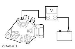
TEST the system for normal operation. | Component Tests Generator On-Vehicle Tests - No-Load Test - Turn off all electrical loads and the ignition switch.
- Switch the multimeter to the voltage function.
- Connect the leads of the multimeter across the battery terminals.
- Read the voltage (base voltage).
- Run the engine at 1500 rpm with no electrical load.
- Read the voltage. The voltage should be in the range of 14.1 volts to 15.1 volts. If the voltage increase is less than 2.5 volts above the base voltage, carry out the Load Test. If the voltage increase is greater than 2.5 volts, REFER to the WDS.
Generator On-Vehicle Tests - Load Test - With the engine running, turn on the air conditioning (if equipped), turn the blower motor to high speed and the headlamps to high beam.
- Increase the engine speed to 2000 rpm. The voltage should increase a minimum of 0.5 volts above the base voltage. If the voltage does not increase as specified, REFER to the WDS. If the voltage increases as specified, the charging system is charging correctly. REFER to the Symptom Chart.
Battery Identification 1 - Cold crank amp (CCA) rating 2 - Reserve capacity (RC) rating (minutes) 6 - EN number (European Norm) 7 - Battery type: Ca = Silver/Calcium; Sb = Lead/Antimony Battery Surface Charge Removal Surface charge dissipation unit (SCD²) 1 - Connect black lead to battery - Connect red lead to battery + 2 - Red A indicator illuminates and green B indicator flashes 3 - Wait until green B indicator illuminates 4 - Disconnect from battery CAUTION:Prior to testing any battery, the surface discharge must be dissipated. This includes batteries that are returned disconnected from the vehicle. If the battery is holding a surface charge, the battery tester will give false readings. NOTE:The SCD² tool eliminates the need to dissipate the battery's surface charge via the manual process of loading the battery via the operation of the vehicles electrical systems. It also removes the variability in the process and makes sure that the actual dissipation of the surface charge is qualified prior to testing. - Connect the black lead to the battery negative terminal and the red lead to the battery positive terminal.
- The red indicator (A) illuminates and the green indicator (B) flashes.
- Wait until the green indicator (B) fully illuminates, then disconnect from the battery.
Alternative Method To Dissipate The Battery Surface Charge - Leave the battery to stand for a minimum of six hours without charging or discharging or remove the surface charge through partial loading as follows:
- Turn the ignition key to position II and switch on the headlamps (main beam), heated windshield (if equipped), heated rear window (if equipped) and the heater blower motor (position II). Leave the vehicle in this condition for a minimum of 60 seconds to dissipate the battery surface charge.
- Turn the ignition key to position 0 and switch off the headlamps, heated windshield (if equipped), heated rear window (if equipped) and the heater blower motor. Leave the vehicle in this condition for a minimum of five minutes before testing battery condition.
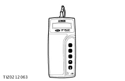
Battery Test NOTE:Using the Micro390 Battery Tester: To fully determine battery condition once the surface charge has been dissipated, the Micro390 battery tester must be used. For the Micro390 battery tester to operate, it requires a minimum of 5.5 volts charge to be present on the test battery. Therefore, if the Micro390 does not operate when connected to a test battery, then a charge of less than 5.5 volts is present. In this instance, the battery must be charged in line with the battery charging instructions prior to testing. In the event of a conflict of results between the charge eye indicator and the battery tester, the battery tester result must always be used. The charge eye indicator is for guidance only. - Connect the battery tester to the battery.
- Connect the red clip to the battery positive (+) terminal and the black clip to the battery negative (–) terminal.
-
NOTE:The label affixed to the top of batteries progressively from 06/1998 identifies the battery CCA rating. Remove the battery if the label is obscured. Use the ”Arrow” buttons on the battery tester to scroll to the battery’s labelled CCA rating. - Press the ”Test” button that corresponds to the correct battery temperature.
- If the battery temperature is above zero degrees centigrade: press the ”sun” button. If the battery temperature is below zero degrees centigrade: press the ”Ice-crystal” button.
- Carry out the action based upon the test result displayed and the following table.
- Charge level bar graph.
- Test result.
- Battery voltage.
- Press the "information" button and carefully note the six-digit "Test Code" on the job card for claim submission and audit purposes (graphic shows an example of the code only).
Battery tester results and required actions | Tester Reading | Action | | GOOD BATTERY | Return to service | | GOOD RECHARGE | Fully charge the battery and return to service* | | CHARGE & RETEST | Fully charge the battery and retest | | REPLACE BATTERY or BAD CELL BATTERY | WARNING:Do not recharge the battery. Make sure that the surface charge was removed. If so, disconnect the battery from the vehicle and retest. If the result remains after surface charge removal, install a new battery. | | UNABLE TO TEST | Disconnect the battery from the vehicle and retest. | *In addition, it is advisable to check the vehicle electrical system. Check that the generator is functioning correctly and that all key-off loads (luggage compartment lamps, glove compartment lamp and interior lamps) are not staying on. |